An installation box for an electric vehicle controller
An electric vehicle controller and installation box technology, applied in vibration suppression adjustment, electrical components, springs/shock absorbers, etc., can solve the problems of controller damage, inconvenient use of trams, and shortened service life of the controller, and achieve guaranteed life. , to ensure the effect of high efficiency and security
- Summary
- Abstract
- Description
- Claims
- Application Information
AI Technical Summary
Problems solved by technology
Method used
Image
Examples
Embodiment 1
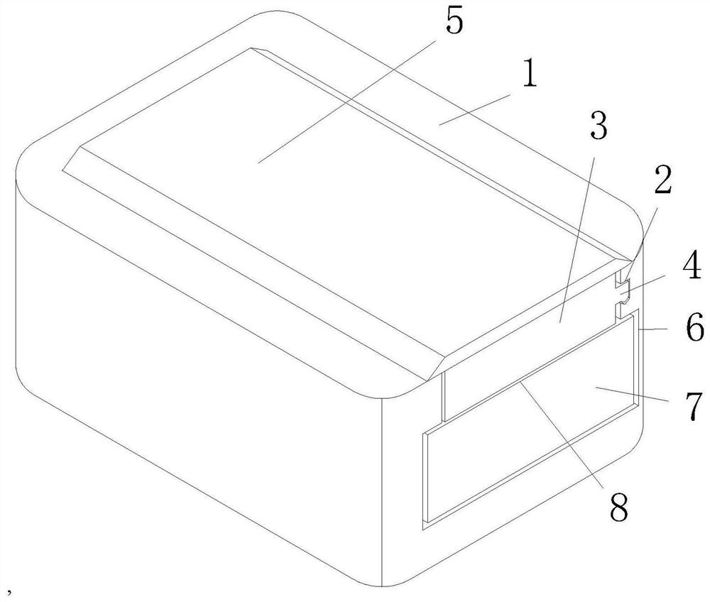
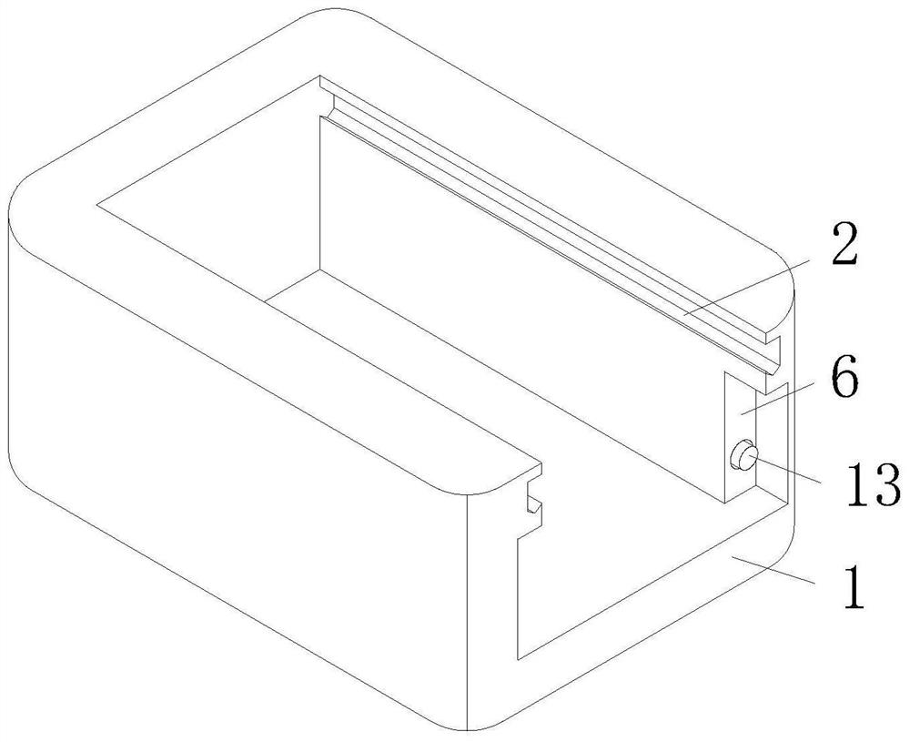
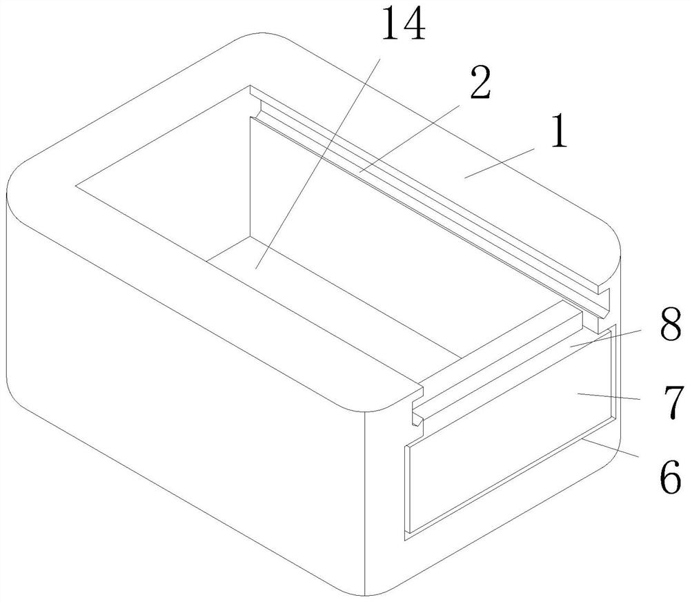
[0036] Example 1: See Figure 1-8, an installation box for an electric vehicle controller, comprising a placement slot 1, a card slot 2 is opened on the inner side of the placement slot 1, a sealing plate 3 is slidably connected to the inside of the placement slot 1, and a clamping plate is fixedly connected to the right side of the sealing plate 3 4. Both the shape of the card slot 2 and the card plate 4 are irregular, the surface of the card plate 4 is slidably connected inside the card slot 2, and the upper side of the sealing plate 3 is fixedly connected with a protective plate 5, and the shape of the protective plate 5 is Isosceles ladder shape, the lower side of the protective plate 5 is slidingly connected with the upper side of the placement groove 1, the inside of the placement groove 1 is provided with a chute 6, the inside of the chute 6 is slidably connected with the upper slide plate 7, and the upper side of the upper slide plate 7 An auxiliary groove 8 is opened,...
Embodiment 2
[0039] Example 2: See Figure 5 , on the basis of Embodiment 1, the cable arrangement device includes a connecting rod 9, the upper end of the connecting rod 9 is slidably connected to the inside of the upper sliding plate 7, the lower end of the connecting rod 9 is fixedly connected to the lower plate 10, and the surface sliding sleeve of the connecting rod 9 Connected with a tension spring 11, the upper and lower ends of the tension spring 11 are respectively fixedly connected to the lower side of the upper slide plate 7 and the upper side of the lower slide plate 10, and the lower side of the upper slide plate 7 and the upper side of the lower slide plate 10 are provided with wire grooves 12. The front side of the lower plate 10 is fixedly connected with a limit rod 13, and the front end of the limit rod 13 is slidably connected to the inside of the placement groove 1.
[0040] When in use, when the upper slide plate 7 is driven by the sealing plate 3 to slide and dock to t...
Embodiment 3
[0041] Example 3: See Figure 4-7 , the damping device includes a placement plate 14, the surface of the placement plate 14 is slidably connected to the inside of the placement groove 1, the lower side of the placement plate 14 is fixedly connected with a buffer rod 15, and the lower end of the buffer rod 15 is slidably connected to the inside of the placement groove 1, The surface of the buffer rod 15 is slidingly sleeved with a buffer spring 16, and the upper and lower ends of the buffer spring 16 are respectively fixedly connected to the lower side of the placement plate 14 and the inside of the placement groove 1, and the upper side of the placement plate 14 is slidably connected to a shock absorbing plate 17. , the upper side of the damping plate 17 is inclined, the surface of the damping plate 17 is slidingly sleeved with a damping spring 18, and the upper and lower ends of the damping spring 18 are fixedly connected to the surface of the damping plate 17 and the bottom o...
PUM
 Abstract
Description
Claims
Application Information
 - R&D
- Intellectual Property
- Life Sciences
- Materials
- Tech Scout
- Unparalleled Data Quality
- Higher Quality Content
- 60% Fewer Hallucinations
Browse by: Latest US Patents, China's latest patents, Technical Efficacy Thesaurus, Application Domain, Technology Topic, Popular Technical Reports.
© 2025 PatSnap. All rights reserved.Legal|Privacy policy|Modern Slavery Act Transparency Statement|Sitemap|About US| Contact US: help@patsnap.com


