Gear switching method of electronic gear shifter

An electronic shifter and gear switching technology, applied in the direction of components with teeth, belts/chains/gears, mechanical equipment, etc., can solve the problem of large size and weight, damage to the transmission structure, and can not meet the requirements of electrification and intelligence and other problems to achieve the effect of avoiding driving hazards and reducing the probability of misoperation

Pending Publication Date: 2021-11-19
JIANGLING MOTORS
View PDF4 Cites 2 Cited by
  • Summary
  • Abstract
  • Description
  • Claims
  • Application Information

AI Technical Summary

Problems solved by technology

However, the traditional mechanical automatic shifter has the following disadvantages: 1. The size and weight are large, and the space requirements for the sub-instrument are relatively high, and the location arrangement is not flexible enough; 2. The mechanical system includes multiple kinematic pairs, such as shift wires and brackets Etc., easy to wear and tear, affecting the smoothness of shifting; 3. It cannot meet the electrification and intelligent requirements of the current automobile industry; 4. In the case of a fault in the reverse gear lock of the shifter, wrongly engaging the reverse gear and the P gear will damage the inside of the transmission 5. The NVH performance is not good, and the NVH on the chassis may be transmitted to the cockpit through the shift wire

Method used


Image

  • Gear switching method of electronic gear shifter
  • Gear switching method of electronic gear shifter
  • Gear switching method of electronic gear shifter

Examples


Embodiment Construction

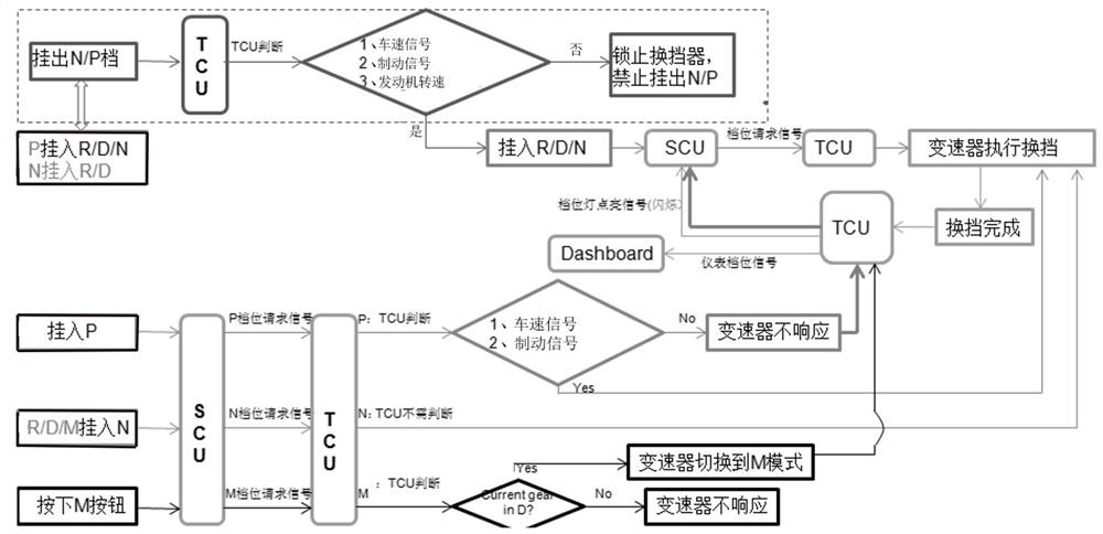
[0027] Refer to the attached figure 1 And embodiment the present invention is described in detail:

[0028] This set of shifting system is mainly composed of knob-type electronic shifter, electronic shifter control module SCU, transmission DCT, and transmission control module TCU, and the signals of each system are exchanged through the CAN bus.

[0029] The meaning of each gear is as follows:

[0030] P parking gear, or parking gear; N neutral gear; R reverse gear; D forward gear or driving gear;

[0031] A gear switching method of an electronic shifter of the present invention, the steps are as follows:

[0032] S1.P shift into R / D / / N gear or N shift into R / D gear:

[0033] S11. After receiving the driver's shift request, the SCU makes a judgment. The judgment conditions at this time are:

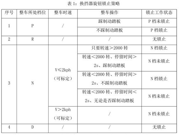
[0034] a. Whether the vehicle speed signal meets the preset requirements, such as the vehicle speed V is less than or equal to the calibration value V 0 ;

[0035] b. Whether the br...


PUM


Abstract

The invention relates to a gear shifting method of an electronic gear shifter, which comprises the following steps of: S1, shifting a P gear into an R/D/N gear or shifting an N gear into the R/D gear: if three conditions of the vehicle speed, braking and the engine rotating speed are met at the same time, completing a gear shifting request, allowing the P gear to be shifted into the R/D/N gear or the N gear to be shifted into the R/D gear, transmitting an instruction to a transmission control unit (TCU) by an SCU, further judging whether the gear shifting condition at the moment is met or not by the TCU, or, locking a knob of the gear shifter to forbid a current gear to be switched into the R/D gear and forbid the current gear to be shifted out of the N/P gear; S2, shifting the current gear into the P gear: directly transmitting a gear shifting request of a driver to the TCU through the SCU, at the moment, judging whether the vehicle speed and braking meet the requirements or not by the TCU, if not, refusing to implement the gear shifting action by the TCU, and if yes, commanding a transmission to be shifted in the P gear by the TCU; and S3, shifting the current gear into the N gear, and directly commanding the transmission to be shifted into the N gear by the TCU. According to the invention, the probability of misoperation of the driver is reduced, and once misoperation occurs, driving dangers are avoided by executing a reliable transmission gear shifting strategy.

Description

technical field [0001] The invention relates to a gear switching method of an electronic gear shifter. Background technique [0002] With the continuous development of new technologies in the automotive industry, more and more low-end automatic transmission models are equipped with electronic shifters. In the process of using the electronic shifter of automatic transmission models, there is a potential danger that many car owners do not pay attention to, that is, the wrong identification and execution of gear positions, and misoperation. Traffic accidents caused by the wrong recognition of the gear position of the electronic shifter and the misoperation of the electronic shift lever occur from time to time, ranging from damage to the vehicle to serious casualties. Therefore, it is necessary to design to prevent the driver from mismanipulating the gear during driving and to minimize the probability of car danger in case of misoperation. It is necessary to design a set of shi...

Claims


Application Information

Patent Timeline
Patent Type & Authority Applications(China)
IPC IPC(8): F16H61/02F16H61/18F16H63/42F16H59/36F16H59/44F16H59/54
CPCF16H61/0213F16H61/18F16H63/42F16H59/44F16H59/54F16H59/36F16H2059/366
Inventor 崔业杰熊倪熊俊祝思敏聂晓龙
Owner JIANGLING MOTORS
Why Eureka
Try Eureka