Gas supply device and sealing gasket replacement method of gas supply device

A technology of gas supply and replacement method, applied in the direction of sealing of engine, method of container discharge, gas/liquid distribution and storage, etc., can solve problems such as increase in manufacturing cost, inability to maintain air tightness, gasket separation, etc.

Active Publication Date: 2021-11-19
KC
View PDF7 Cites 0 Cited by
  • Summary
  • Abstract
  • Description
  • Claims
  • Application Information

AI Technical Summary

Problems solved by technology

[0006] As mentioned above, in the case where the gasket sticks to the valve connector, there is no additional mechanism to sense this, and in order to confirm the seal with a sensing sensor or the like Whether the pad is bonded or not requires additional parts, and therefore there is a problem that the manufacturing cost of the device increases
[0007] If the gasket for the valve connector is still bonded, join the piping connector after bonding a new gasket to the connecting piping connector and valve connector, since two gaskets (existing gasket and new gasket) are inserted between the connecting pipe connector and the valve connector in a double-insert manner, it may occur that airtightness cannot be maintained. gas leak accident
[0008] And, transfer the connection piping connector in the state where the new gasket is connected to the connection piping connector and connect the connection piping connector to the valve connector, During the transfer of the connecting pipe connector, there may be a problem that the new gasket may be detached from the connecting pipe connector

Method used


Image

  • Gas supply device and sealing gasket replacement method of gas supply device
  • Gas supply device and sealing gasket replacement method of gas supply device
  • Gas supply device and sealing gasket replacement method of gas supply device

Examples


Embodiment Construction

[0071] The present invention will be described in detail below with reference to the accompanying drawings.

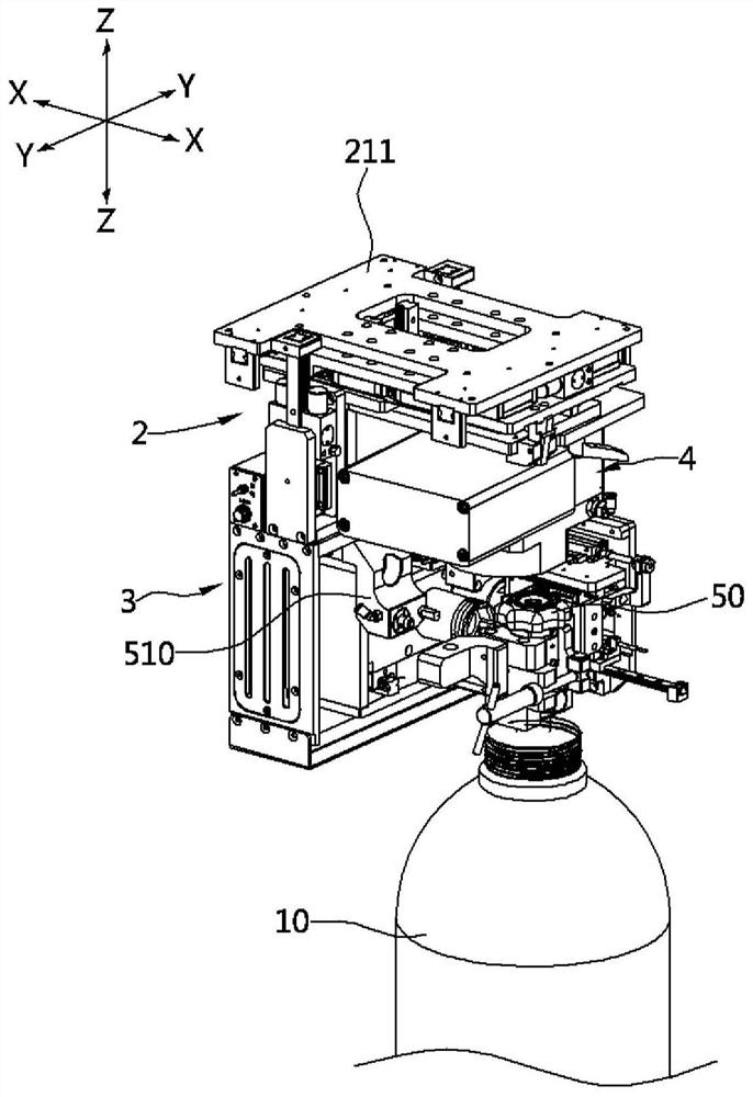
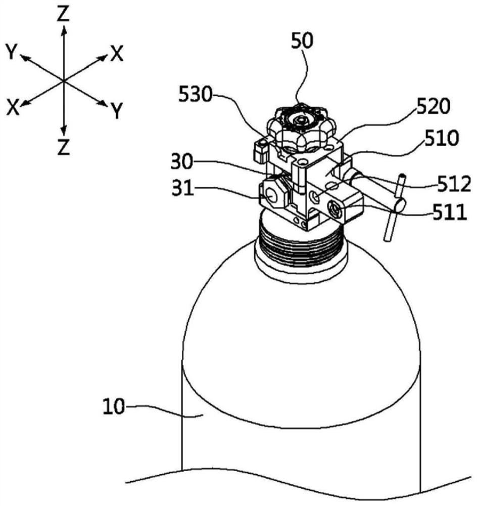
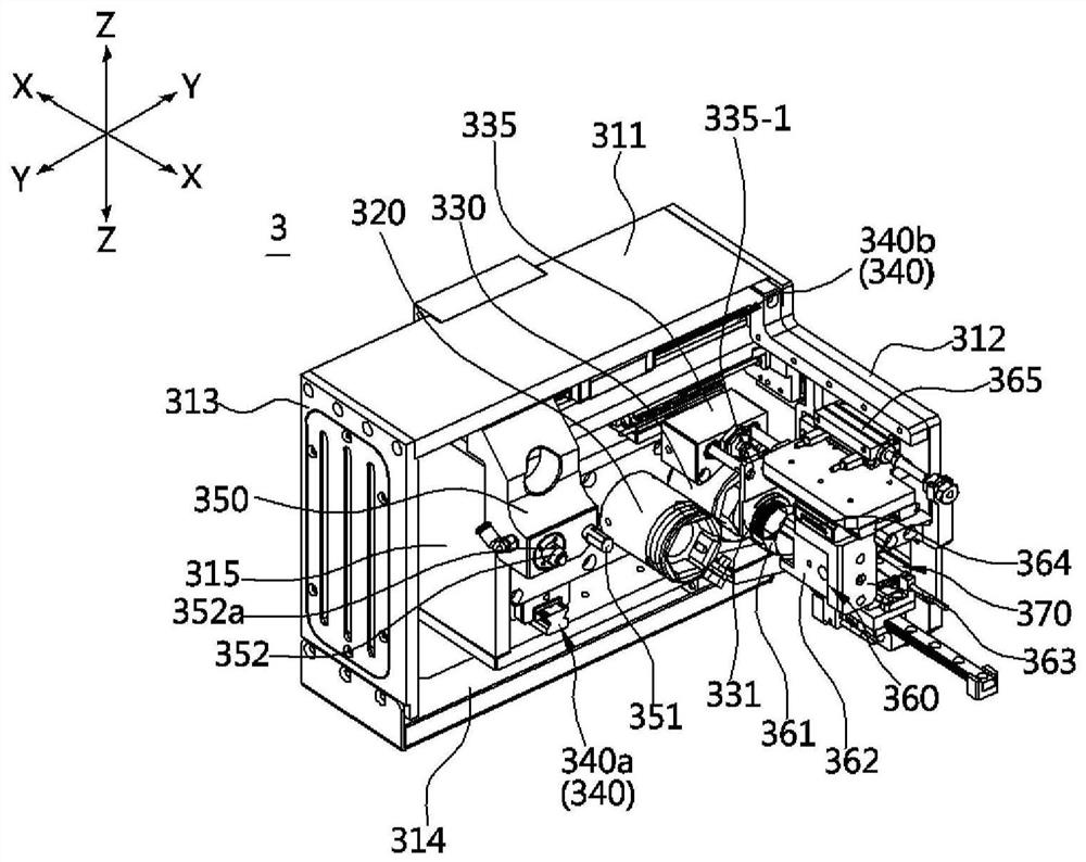
[0072] Here, when referring to the direction, the figure 1 The shown X-axis is called the front-back direction, the Y-axis is called the left-right direction, and the Z-axis is called the vertical direction. In addition, the horizontal direction includes the above-mentioned left-right direction and front-rear direction formed by the XY plane. Also, when distinguishing the front and rear directions, the side where the container 10 is arranged is called the front, and the side where the lower module 3 is arranged is called the rear. And, when distinguishing the left and right directions based on the cover separation part 320 and the connector fastening part 330, the side where the cover separation part 320 is arranged is defined as the right side, and the side where the connector fastening part 330 is arranged is defined as the right side. This side is defined as the l...


PUM


Abstract

The purpose of the present invention is to provide a gas supply device and a sealing gasket replacement method capable of preventing double insertion of a gasket due to adhesion of the gasket to a valve connector of a container. The sealing gasket replacement method of a gas supply device according to the present invention comprises the steps of: a) placing a sealing gasket between a valve connector provided in a container and a connection piping connector connected to a gas demand site to couple the valve connector and the connection piping connector; b) releasing the coupling of the valve connector and the connecting piping connector; and c) transferring the sealing gasket after separating the sealing gasket from between the valve connector and the connecting piping connector, wherein the process of performing the steps a) to c) includes a process in which the sealing gasket is gripped by a sealing gasket gripper and the sealing gasket gripper gripping the sealing gasket and the connecting piping connector are simultaneously transferred.

Description

technical field [0001] The present invention relates to a gas supply device and a gasket replacement method, and more particularly, to a gas supply device and a gasket replacement method capable of preventing the gasket from coming off and from a situation where the gasket is stuck to a valve connector of a container. Background technique [0002] In general, for devices that supply gas to devices using gas (particularly, where gas is demanded for fine operations such as semiconductor equipment, etc.), types of gas suitable for various purposes are required to satisfy predetermined concentrations, pressures, and the like. [0003] In order to efficiently supply such gases, many kinds of gases are kept under high pressure. In particular, gases with harmful properties such as flammability, toxicity, and corrosion are strictly managed in separate spaces separated from humans. [0004] The gas storage container (hereafter, simply referred to as "container") for storing gas is co...

Claims


Application Information

Patent Timeline
Patent Type & Authority Applications(China)
IPC IPC(8): F17C13/00F17C13/04F17C13/06
CPCF17C13/00F17C13/04F17C13/06F17C2223/0123F17C2270/0518F17C13/002B25J15/08B25B27/0028F16J15/02F17C7/02H01L21/67017F17C2205/037F17C2201/0104F17C2201/056
Inventor 朴用建李祥煜金容澈徐彻教金相镇
Owner KC
Why Eureka
Try Eureka