Motor shell and motor stator structure

A technology for motor stator and motor casing, which is applied in the direction of casing/cover/support, magnetic circuit shape/style/structure, electrical components, etc. problems, to achieve the effect of facilitating automatic assembly, reducing clearance vibration, and stable stator structure

Active Publication Date: 2021-11-26
南昌耀德精密五金有限公司
View PDF10 Cites 0 Cited by
  • Summary
  • Abstract
  • Description
  • Claims
  • Application Information

AI Technical Summary

Problems solved by technology

The motor shell is an important part of the motor, which mainly plays the role of load-bearing installation and heat dissipation. During the use of the motor, the coil is energized. Due to the resistance effect, the coil will generate heat, and the heat will be conducted from the iron chip to the shell, while the traditional motor shell The structure is simple, and the heat conduction with the outside air is not fast enough, so the heat dissipation effect is poor and the practicability is not strong, and the heat cannot be dissipated for a long time, which will cause the coil to overheat, and then burn the coil to cause motor failure. The casing is of one-piece structure. When used for a long time, the casing is prone to rust as a whole. The rust layer will affect the heat dissipation effect of the motor casing. Therefore, some motor casings will be coated with anti-rust paint for rust prevention. The anti-rust layer will affect the heat dissipation of the heat dissipation part. heat radiation
The motor stator is one of the important components of the motor that can convert electrical energy into mechanical energy. It works by generating magnetic force after the coil is energized, and pushing the rotor to generate torque. Traditional motor electronics are composed of multiple iron chips and coils, but the traditional The fixed iron chips are loosely stacked, which is prone to loosening during long-term use, and will also cause friction with the motor rotor, resulting in the scrapping of the motor

Method used


Image

  • Motor shell and motor stator structure
  • Motor shell and motor stator structure
  • Motor shell and motor stator structure

Examples


Embodiment Construction

[0039] The technical solutions in the embodiments of the present invention will be clearly and completely described below in conjunction with the accompanying drawings in the embodiments of the present invention. Obviously, the described embodiments are only some of the embodiments of the present invention, not all of them. To simplify the disclosure of the present invention, the components and arrangements of specific examples are described below, which, of course, are examples only and are not intended to limit the present invention.

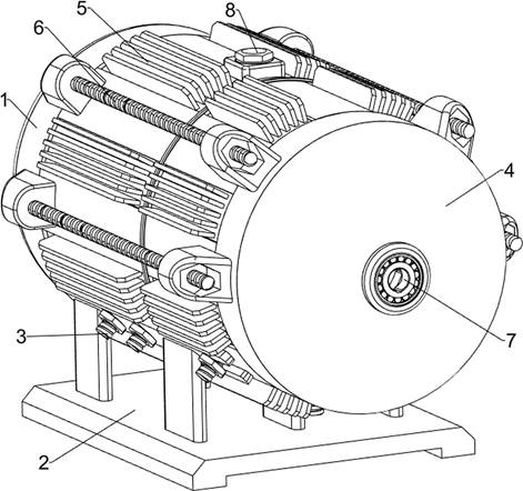
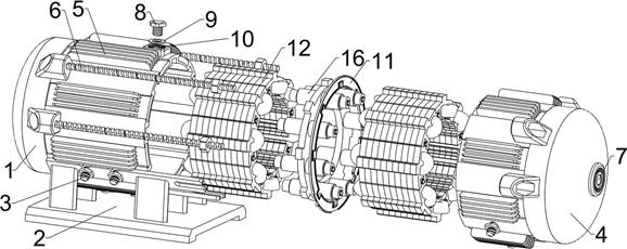
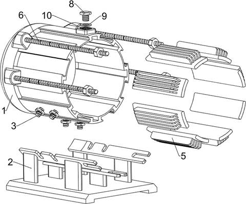
[0040] Below, the structure of the motor casing and the motor stator according to the embodiment of the present invention will be described with reference to the accompanying drawings, such as figure 2 , image 3 and Figure 4 As shown, the motor casing and the motor stator structure include a fixing device, and the fixing device includes a first housing 1, a base 2, a first bolt 3 and a second housing 4, and the first housing 1 and the seco...


PUM


Abstract

The invention aims to provide a motor shell and motor stator structure, and the structure comprises a heat dissipation device and a bridging assembly; the heat dissipation device is composed of soaking plates, the soaking plates are uniformly distributed at the outer sides of a first shell and a second shell, and vertical plates at the outer sides are fully contacted with air to dissipate heat and carry out rapid heat dissipation; the bridging assembly comprises a mounting plate, a first connecting column, a second connecting column and a spring, the mounting plate is slidably mounted in the first shell, the first connecting column and the second connecting column are slidably mounted on the mounting plate after being connected through the spring, and the stator structures on the two sides are fixed under the action of the spring, so that an iron core sheet is fully pressed, and vibration is avoided. Meanwhile, the bridging assembly made of conductive materials enables the stator structures on the two sides to be communicated, and normal operation of the stator structures on the two sides is guaranteed.

Description

technical field [0001] The invention relates to the technical field of motors, in particular to a motor casing and a motor stator structure. Background technique [0002] Motors are commonly used accessories in mechanical equipment, which can convert electrical energy into mechanical energy and then perform work. The motor shell is an important part of the motor, which mainly plays the role of load-bearing installation and heat dissipation. During the use of the motor, the coil is energized. Due to the resistance effect, the coil will generate heat, and the heat will be conducted from the iron chip to the shell, while the traditional motor shell The structure is simple, and the heat conduction with the outside air is not fast enough, so the heat dissipation effect is poor and the practicability is not strong, and the heat cannot be dissipated for a long time, which will cause the coil to overheat, and then burn the coil to cause motor failure. The casing is of one-piece str...

Claims


Application Information

Patent Timeline
Patent Type & Authority Applications(China)
IPC IPC(8): H02K5/04H02K5/18H02K5/02H02K1/18H02K5/22H02K5/24H02K16/04
CPCH02K5/04H02K5/18H02K5/02H02K1/185H02K5/225H02K5/24H02K16/04
Inventor 黄淑芳
Owner 南昌耀德精密五金有限公司
Why Eureka
Try Eureka