Indoor and outdoor scene switching positioning device and method

A technology for scene switching and positioning devices, which is applied in the direction of measuring devices, location information-based services, satellite radio beacon positioning systems, etc., and can solve the problem of large errors in combined positioning modules, unsustainable accuracy of centimeter-level stability, and inability to meet high precision real-time positioning

Pending Publication Date: 2021-11-30
中铝视拓智能科技有限公司 +2
View PDF0 Cites 1 Cited by
  • Summary
  • Abstract
  • Description
  • Claims
  • Application Information

AI Technical Summary

Problems solved by technology

[0003] The UWB positioning module and RTK positioning module can achieve centimeter-level accuracy in their signal coverage area, but when the combined positioning module moves from the indoor area to the outdoor area, the RTK positioning module needs a certain amount of time to search for satellites to obtain a high-precision fixed solution. The module loses accuracy due to being far away from the base station. During this period of time, the error of the combined positioning module is relatively large, which cannot meet the needs of high-precision real-time positioning.
[0004] In the existing technology, auxiliary sensors, Bluetooth, WIFI and other methods are used for indoor and outdoor seamless positioning, but the accuracy of these methods cannot reach the centimeter level continuously and stably, and are not suitable for such as vehicle obstacle avoidance, mobile industrial equipment early warning and obstacle avoidance Situations that require real-time high-precision positioning information

Method used


Image

  • Indoor and outdoor scene switching positioning device and method
  • Indoor and outdoor scene switching positioning device and method
  • Indoor and outdoor scene switching positioning device and method

Examples


Embodiment Construction

[0056] The principles and features of the present invention are described below in conjunction with the accompanying drawings, and the examples given are only used to explain the present invention, and are not intended to limit the scope of the present invention.

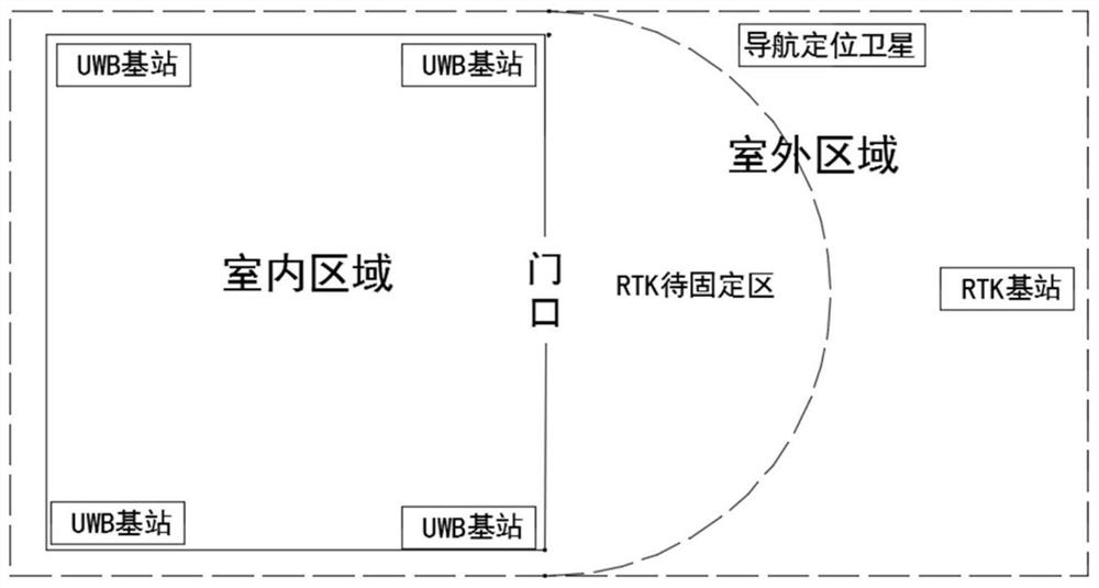
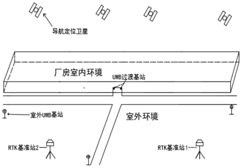
[0057] An indoor and outdoor scene switching positioning device, such as figure 1 As shown, including UWB base station, RTK base station and combined positioning terminal;

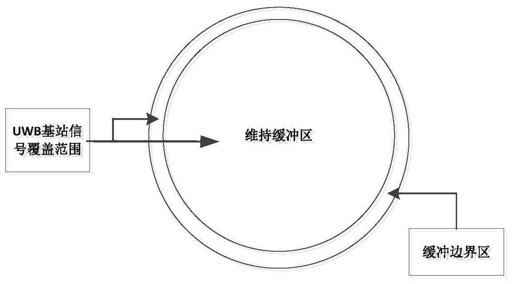
[0058] Taking the entrance and exit of the target building as the center and using the preset distance as the radius to define a maintenance buffer zone, and the UWB base station is set in the maintenance buffer zone;

[0059] The UWB base station is configured to send a positioning signal to the combined positioning terminal;

[0060] The area where the coverage of the UWB base station signal and the maintenance buffer does not intersect is defined as a maintenance buffer boundary area; the RTK base station is set in the maintenance buffer bou...


PUM


Abstract

The invention relates to an indoor and outdoor scene switching positioning device and method. The device comprises a UWB base station, an RTK base station and a combined positioning terminal. A maintenance buffer area is defined by taking the entrance and exit of the target building as the circle center and taking a preset distance as the radius, and the UWB base station is arranged in the maintenance buffer area; the UWB base station is used for sending a positioning signal to the combined positioning terminal; an area where the coverage area of the UWB base station signal is not crossed with the maintenance buffer area is defined as a maintenance buffer boundary area; the RTK base station is arranged in the maintenance buffer boundary area; the RTK base station is used for sending a differential signal to the combined positioning terminal; the combined positioning terminal is in communication connection with the UWB base station and the RTK base station; and the combined positioning terminal is used for obtaining own positioning coordinates according to the positioning signal and the differential signal. Through indoor and outdoor combination of the UWB base station and the RTK base station, when the combined positioning terminal moves from an indoor scene to an outdoor scene, high-precision positioning can still be continuously and stably maintained, and indoor and outdoor seamless positioning with centimeter-level precision is realized.

Description

technical field [0001] The present invention relates to the technical field of indoor and outdoor positioning, in particular to an indoor and outdoor scene switching positioning device and method. Background technique [0002] In recent years, with the gradual maturity of wireless positioning technology, the location-based service industry has developed rapidly. For example, smart city construction, Internet of Things, industrial supervision and other fields all need location-based services. Real-time dynamic carrier phase difference (RTK) positioning technology is widely used in various fields in the surveying and mapping industry. It is easy to use outdoors and can cover the outdoor range of industrial parks to meet the needs of real-time high-precision positioning in outdoor environments. However, due to the obstruction of satellite signals by buildings , RTK cannot obtain a fixed solution in an indoor environment, and the positioning accuracy is low. In the field of ind...

Claims


Application Information

Patent Timeline
Patent Type & Authority Applications(China)
IPC IPC(8): G01S19/46G01S19/41H04W4/02H04W4/021H04W4/33H04W64/00
CPCG01S19/46G01S19/41H04W4/021H04W4/023H04W4/33H04W64/00
Inventor 班剑锋董楠滕振勋张扬帆高小平褚宏梅蒙金龙杜云集王平覃泽颖唐诗华
Owner 中铝视拓智能科技有限公司
Why Eureka
Try Eureka