Cabinet cabling rack convenient for limited rotation of electric wire and cabinet

A technology for wiring racks and cabinets, which is applied to the installation of electrical components, electrical equipment components, and support structures, which can solve the problem of inconvenient maintenance and replacement of a single wire, and achieve the effect of easy maintenance and replacement

Active Publication Date: 2021-11-30
安徽海兴科技设备有限公司
View PDF10 Cites 0 Cited by
  • Summary
  • Abstract
  • Description
  • Claims
  • Application Information

AI Technical Summary

Problems solved by technology

[0004] The purpose of the present invention is to provide a cabinet cable rack and a cabinet that are convenient for the limited rotation of electric wires, so as to solve the problem that the cable rack in the prior art is inconvenient to maintain and replace a single wire

Method used


Image

  • Cabinet cabling rack convenient for limited rotation of electric wire and cabinet
  • Cabinet cabling rack convenient for limited rotation of electric wire and cabinet
  • Cabinet cabling rack convenient for limited rotation of electric wire and cabinet

Examples


Embodiment Construction

[0022] The following will clearly and completely describe the technical solutions in the embodiments of the present invention with reference to the drawings in the embodiments of the present invention.

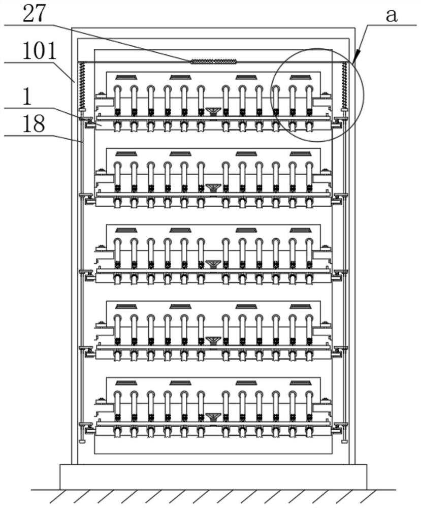
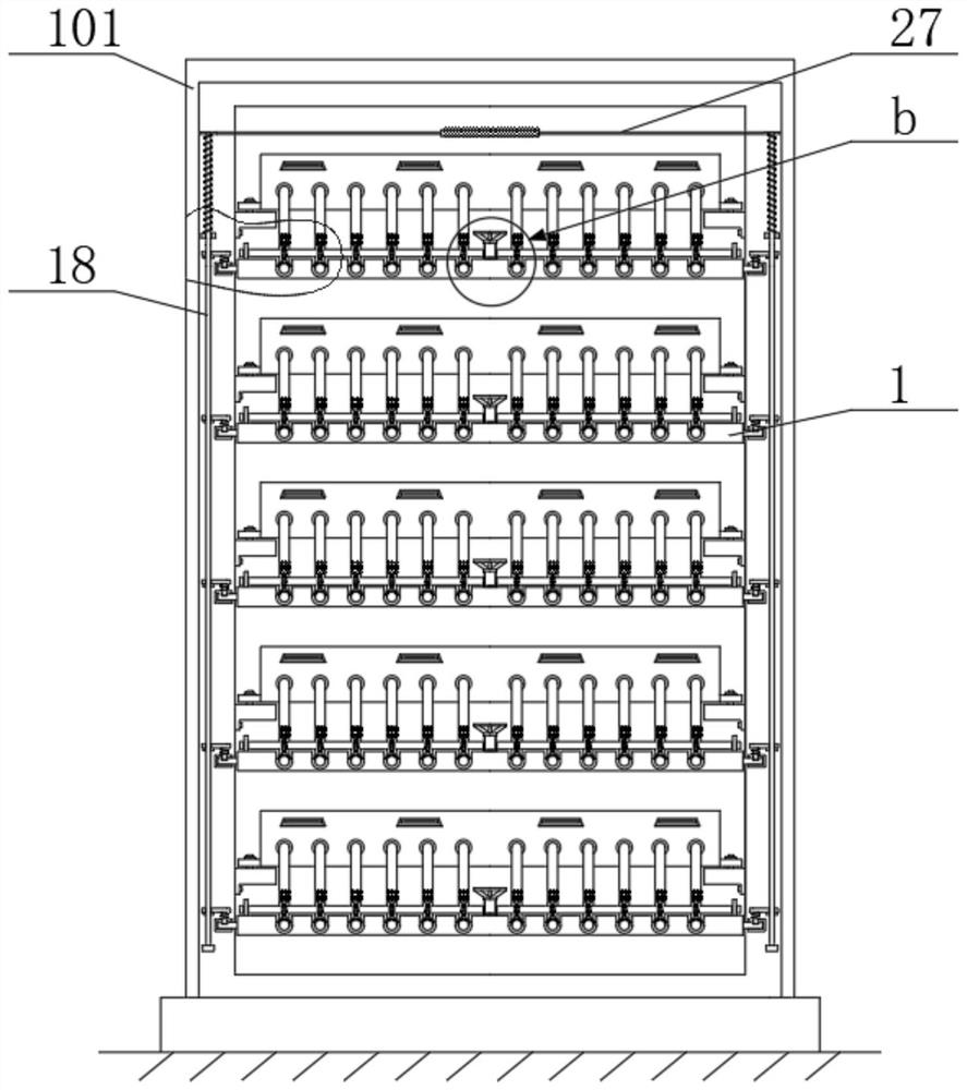
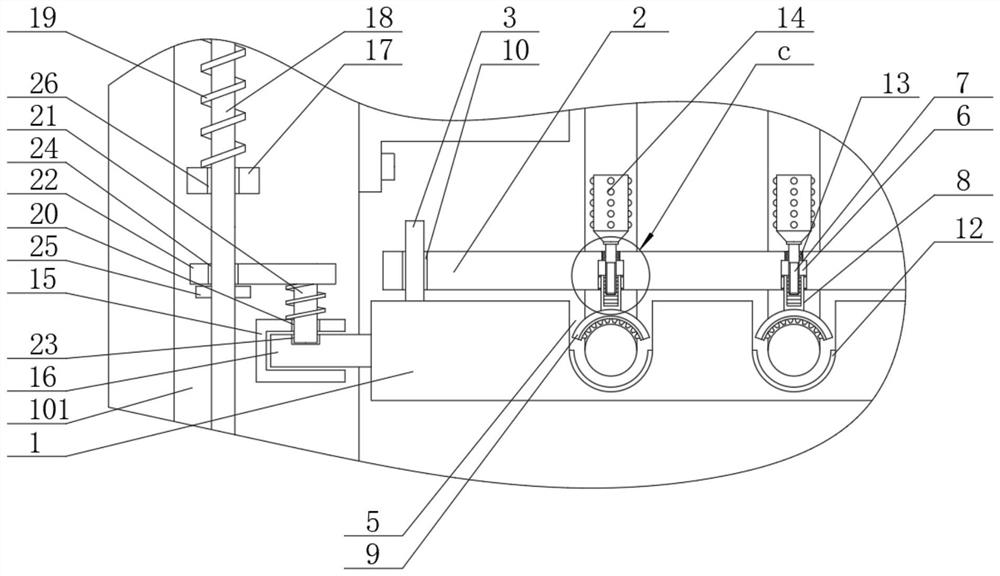
[0023] see Figure 1-6 , a cabinet cable rack that facilitates the limited rotation of wires, including a cabinet body 101 and a release plate 1 arranged on it, the upper end of the release plate 1 is provided with an adjustment plate 2, and the upper end of the release plate 1 is located on both sides and in the middle. The limiting rod 3 and the adjusting screw 4 are arranged respectively, the limiting rod 3 runs through the adjusting plate 2, the thread of the adjusting screw 4 runs through the adjusting plate 2, and the upper end surface of the pay-off plate 1 is provided with a wire groove 5;

[0024] The adjusting screw 4 is installed on the pay-off plate 1 through the rotation of the bearing seat, the two sides of the upper end of the adjusting plate 2 and the middle po...


PUM


Abstract

The present invention discloses a cabinet cabling rack convenient for limited rotation of an electric wire and cabinet. The cabinet cabling rack comprises an equipment cabinet body and a pay-off plate arranged on the equipment cabinet body, an adjusting plate is arranged at the upper end of the pay-off plate, a limiting rod and a rotationally-arranged adjusting screw rod are arranged on the two sides and the middle position of the upper end of the pay-off plate respectively, and the limiting rod penetrates through the adjusting plate; and the adjusting screw penetrates through the adjusting plate in a threaded mode, a wire groove is formed in the upper end face of the pay-off plate, a stepped hole is correspondingly formed in the adjusting plate, a jacking screw is rotationally arranged in the stepped hole, an inner threaded sleeve is arranged at the bottom end of the jacking screw in a threaded and sleeved mode, a wire clamping block is arranged at the bottom end of the inner threaded sleeve, and the bottom end of the wire clamping block is inserted into the wire groove. Through the arrangement of a vertical rod, a return spring, a connecting block, a fixing block, a reset spring sleeve rod and a connecting plate, rapid installation of a wire group is facilitated, and under the cooperation of an adjusting plate, a limiting rod, an adjusting screw rod, a jacking screw rod, an internal thread sleeve and a wire clamping block, rapid maintenance and replacement of a single wire are facilitated.

Description

technical field [0001] The invention belongs to the technical field of wire routing frames, and in particular relates to a cabinet routing frame and a cabinet that facilitate the limited rotation of electric wires. Background technique [0002] The cable tray is also called the cable tray, which is a special equipment for wiring in the computer room. After entering the computer room of telecommunications, Netcom, and radio and television, the light and cable enter the terminal equipment through the cable frame. It is used for binding the light and cable. shelf. [0003] A cabinet is a free-standing or self-supporting enclosure used to house electrical or electronic equipment, generally equipped with doors, removable or non-removable side panels, and a back panel, on which multiple electrical equipment, such as servers, are placed side by side vertically , a single electrical device will connect multiple wires, called a group, in order to avoid entanglement of the wires betw...

Claims


Application Information

Patent Timeline
Patent Type & Authority Applications(China)
IPC IPC(8): H05K7/14
CPCH05K7/1447
Inventor 吴中仁
Owner 安徽海兴科技设备有限公司
Why Eureka
Try Eureka