Flue gas emission system and desulfurization device of power plant

A flue gas emission and power plant technology, applied to the separation of dispersed particles, chemical instruments and methods, separation methods, etc., can solve the problems of water vapor entry, waste of water resources, white feathers at the chimney outlet, etc., to reduce temperature and humidity, and reduce water pollution. Consumption, reduce the effect of project cost

Pending Publication Date: 2019-05-10
王剑
View PDF0 Cites 0 Cited by
  • Summary
  • Abstract
  • Description
  • Claims
  • Application Information

AI Technical Summary

Problems solved by technology

[0002] At present, after wet desulfurization of most coal-fired boilers, the net flue gas of about 45-60°C is directly or indirectly (heated to 75-85°C) discharged through the ch

Method used


Image

  • Flue gas emission system and desulfurization device of power plant
  • Flue gas emission system and desulfurization device of power plant
  • Flue gas emission system and desulfurization device of power plant

Examples


Embodiment 1

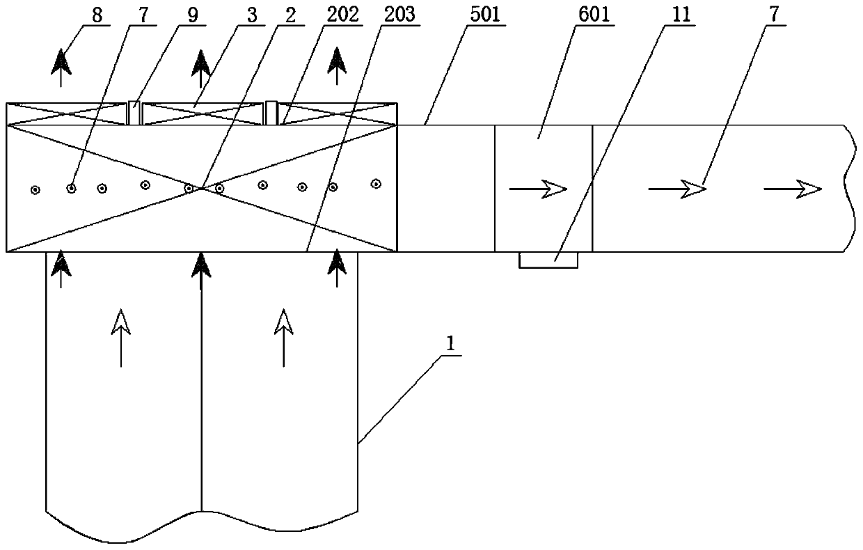
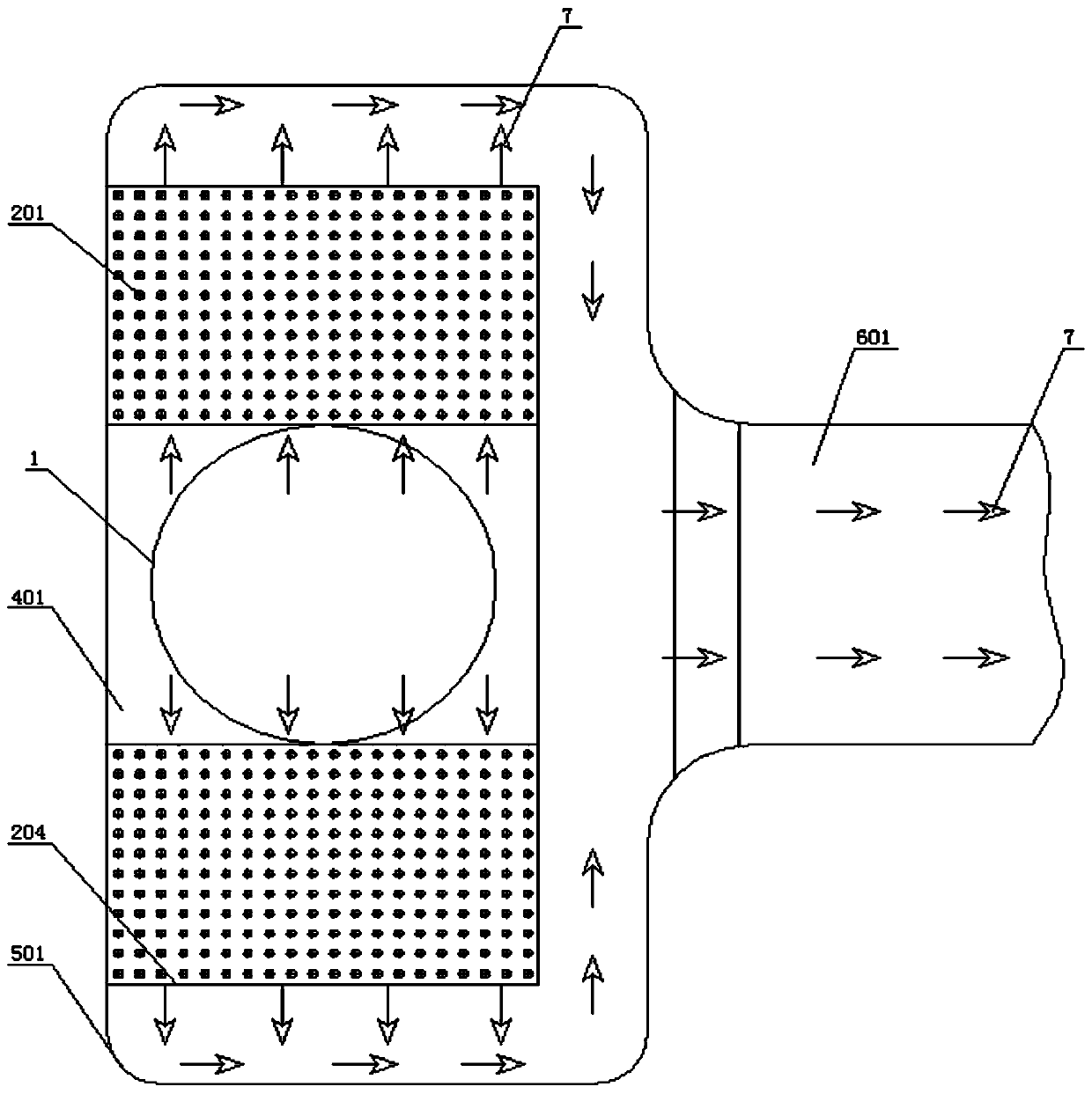
[0035] A power plant flue gas exhaust system, such as figure 1 with figure 2 As shown, including the desulfurization tower 1, the top of the desulfurization tower 1 is provided with a tubular heat exchanger 2, and the tubular heat exchanger 2 is directly connected to the desulfurization tower 1 through the air intake air box to introduce the desulfurized wet and clean flue gas, which will be lower than the wet flue gas. The ambient air of the clean flue gas is introduced into the heat exchange tube 201 of the tubular heat exchanger 2 as a cold medium, and the wet and clean flue gas desulfurized by the desulfurization tower 1 is heat-exchanged and condensed, and the clean flue gas after heat exchange enters the belt The exhaust channel of the liquid collection tank 11, the liquid collection tank 11 is arranged at the low point of the exhaust channel.

[0036] In this embodiment, a water spray or spray system is installed at the inlet of the cooling medium of the tubular heat ...

Embodiment 2

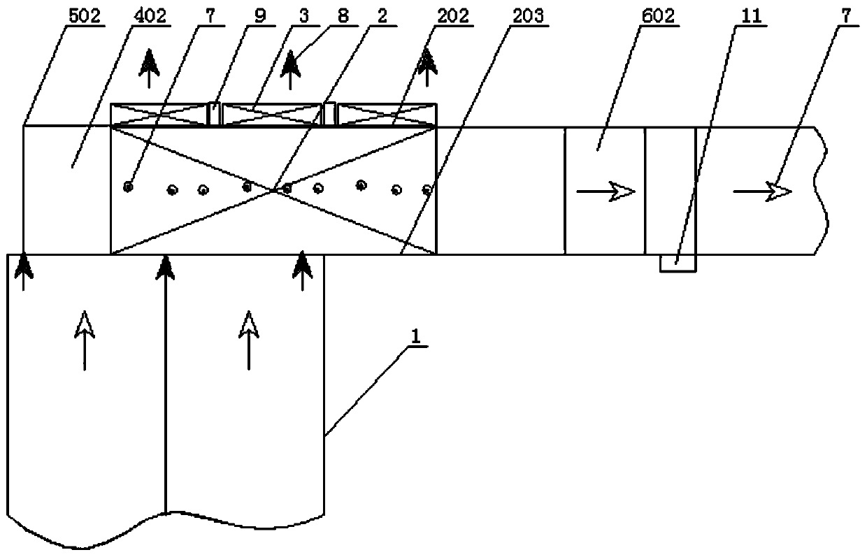
[0049] A power plant flue gas exhaust system, such as image 3 with Figure 4 As shown, including the desulfurization tower 1, the top of the desulfurization tower 1 is provided with a tubular heat exchanger 2, and the tubular heat exchanger 2 is directly connected to the desulfurization tower 1 through the air intake air box to introduce the desulfurized wet and clean flue gas, which will be lower than the wet flue gas. The ambient air of the clean flue gas is introduced into the heat exchange tube 201 of the tubular heat exchanger 2 as a cold medium, and the wet and clean flue gas desulfurized by the desulfurization tower 1 is heat-exchanged and condensed, and the clean flue gas after heat exchange enters the belt The exhaust channel of the liquid collection tank 11, the liquid collection tank 11 is arranged at the low point of the exhaust channel.

[0050] In this embodiment, a water spray or spray system is installed at the inlet of the cooling medium of the tubular heat ...

Embodiment 3

[0062] A power plant flue gas exhaust system, such as Figure 5 with Image 6 As shown, including the desulfurization tower 1, the top of the desulfurization tower 1 is provided with a tubular heat exchanger 2, and the tubular heat exchanger 2 is directly connected to the desulfurization tower 1 through the air intake air box to introduce the desulfurized wet and clean flue gas, which will be lower than the wet flue gas. The ambient air of the clean flue gas is introduced into the heat exchange tube 201 of the tubular heat exchanger 2 as a cold medium, and the wet and clean flue gas desulfurized by the desulfurization tower 1 is heat-exchanged and condensed, and the clean flue gas after heat exchange enters the belt The exhaust channel of the liquid collection tank 11, the liquid collection tank 11 is arranged at the low point of the exhaust channel.

[0063] In this embodiment, a water spray or spray system is installed at the inlet of the cooling medium of the tubular heat ...


PUM


Abstract

The invention provides a flue gas emission system of a power plant. The flue gas emission system of the power plant comprises a desulphurization tower, wherein a tubular heat exchanger is arranged atthe top of the desulphurization tower; the tubular heat exchanger is directly communicated with desulphurized wet clean flue gas introduced into the desulphurization tower by virtue of an air inlet bellow; ambient air which is lower than the wet clean flue gas is introduced into a heat exchange pipe of the tubular heat exchanger as a cold medium to cool the wet clean flue gas after being desulphurized by the desulphurization tower; the heat exchanged clean flue gas enters an exhaust passage with a liquid collecting tank; and the liquid collecting tank is used for recovering condensed water andis arranged at a low point of the exhaust passage. The flue gas emission system can not only recover the water resources and waste heat, but also can reduce the occupied area of land, reduce the construction cost, shorten the construction period, reduce the energy consumption and water consumption, and also effectively eliminate'white feather'.

Description

technical field [0001] The invention relates to a coal-fired boiler system of a power plant, in particular to a flue gas discharge system and a desulfurization device of a power plant. Background technique [0002] At present, after wet desulfurization of most coal-fired boilers, the net flue gas of about 45-60°C is directly or indirectly (heated to 75-85°C) discharged through the chimney, causing a large amount of water vapor to enter the atmosphere, which wastes water resources and also wastes water. A "white feather" phenomenon appears at the chimney outlet. As the country has higher and stricter requirements on the environmental discharge and comprehensive utilization of water resources of coal-fired boiler units in thermal power plants, it is becoming more and more important to save energy and water and eliminate "white feathers". [0003] The "white feather" of flue gas is caused by the condensation of water vapor in the flue gas discharged into the atmosphere, and th...

Claims


Application Information

Patent Timeline
IPC IPC(8): B01D53/78B01D53/00
Inventor 王键廖光亚周杰王磊
Owner 王剑
Why Eureka
Try Eureka