
Managing data center airflow

a data center and airflow technology, applied in the direction of electrical equipment, electrical apparatus, electrical apparatus contruction details, etc., can solve the problems of increasing the cost of airflow removal, and increasing the cost of airflow, so as to reduce the temperature of the outside airflow of the dry bulb

Active Publication Date: 2016-04-12
GOOGLE LLC
View PDF25 Cites 46 Cited by
  • Summary
  • Abstract
  • Description
  • Claims
  • Application Information

AI Technical Summary

Benefits of technology

The invention is a system and method for cooling electronic equipment using a direct evaporative cooling module. This module helps clean the air by precipitating out contaminants with a cooling fluid, which can be adjusted based on the detection of contaminants in the air. This cooling system eliminates the risks of using outside air for data center cooling and increases energy efficiency by employing multiple modes of supply air cooling based on environmental conditions. This system also reduces water usage, which increases its energy efficiency and makes it more environmentally-friendly and impact-less on site resources.

Problems solved by technology

Many forget that this speed often comes with a cost—higher power consumption.
Thus, the cost of removing all of the heat can also be a major cost of operating large data centers.
That cost typically involves the use of even more energy, in the form of electricity and natural gas, to operate chillers, condensers, pumps, fans, cooling towers, and other related components.
Heat removal can also be important because, although microprocessors may not be as sensitive to heat as are people, increases in temperature can cause great increases in microprocessor errors and failures.
In sum, a data center requires a large amount of electricity to power the critical load, and even more electricity to cool the load.
But air side economization also may have an inherent risk of introducing outside air into a relatively clean space.
At worst, outside environmental conditions may include contaminants (e.g., ash, chemicals, biologic material, exhaust from hydrocarbon powered generators, NOx gases) from disasters, such as fires, chemical spills, airborne terrorist attacks, or other calamities.
The introduction of such hazards into a cooling airflow can affect server reliability, performance, and life.
Inherent risks associated with using outside air for data center cooling, such as supply air contamination, are mitigated without employing expensive mechanical cooling techniques.

Method used


Image

  • Managing data center airflow
  • Managing data center airflow
  • Managing data center airflow

Examples


Embodiment Construction

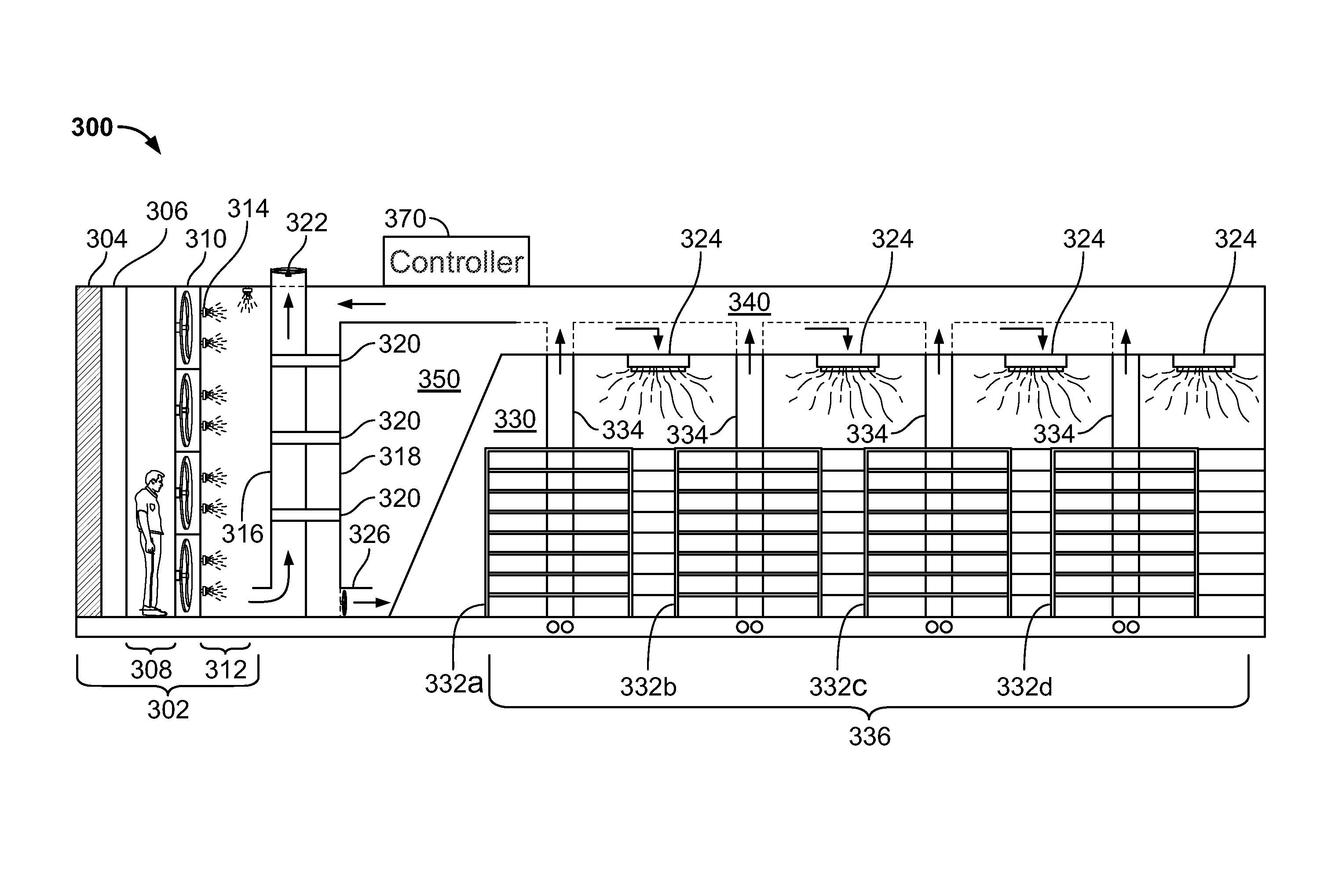
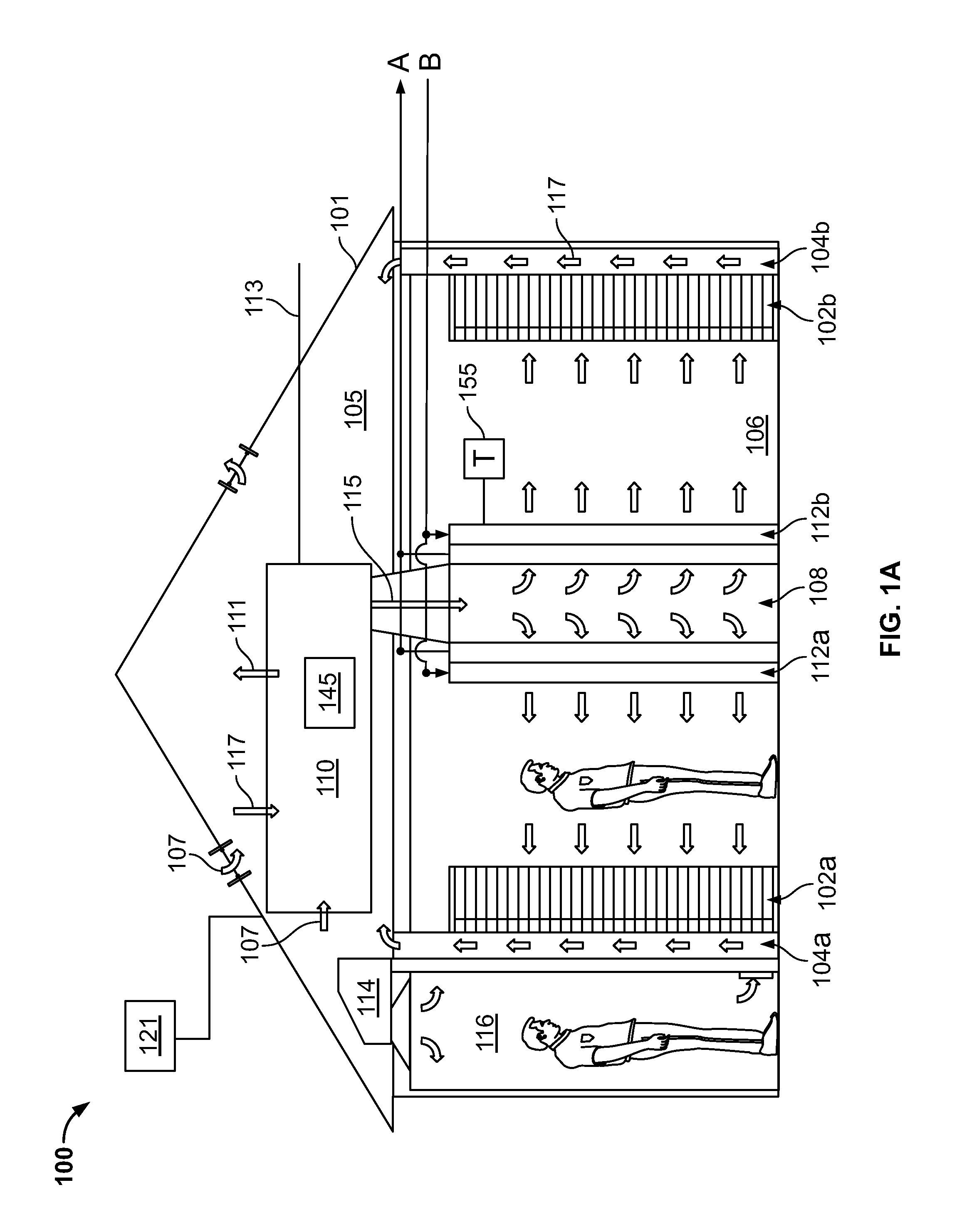
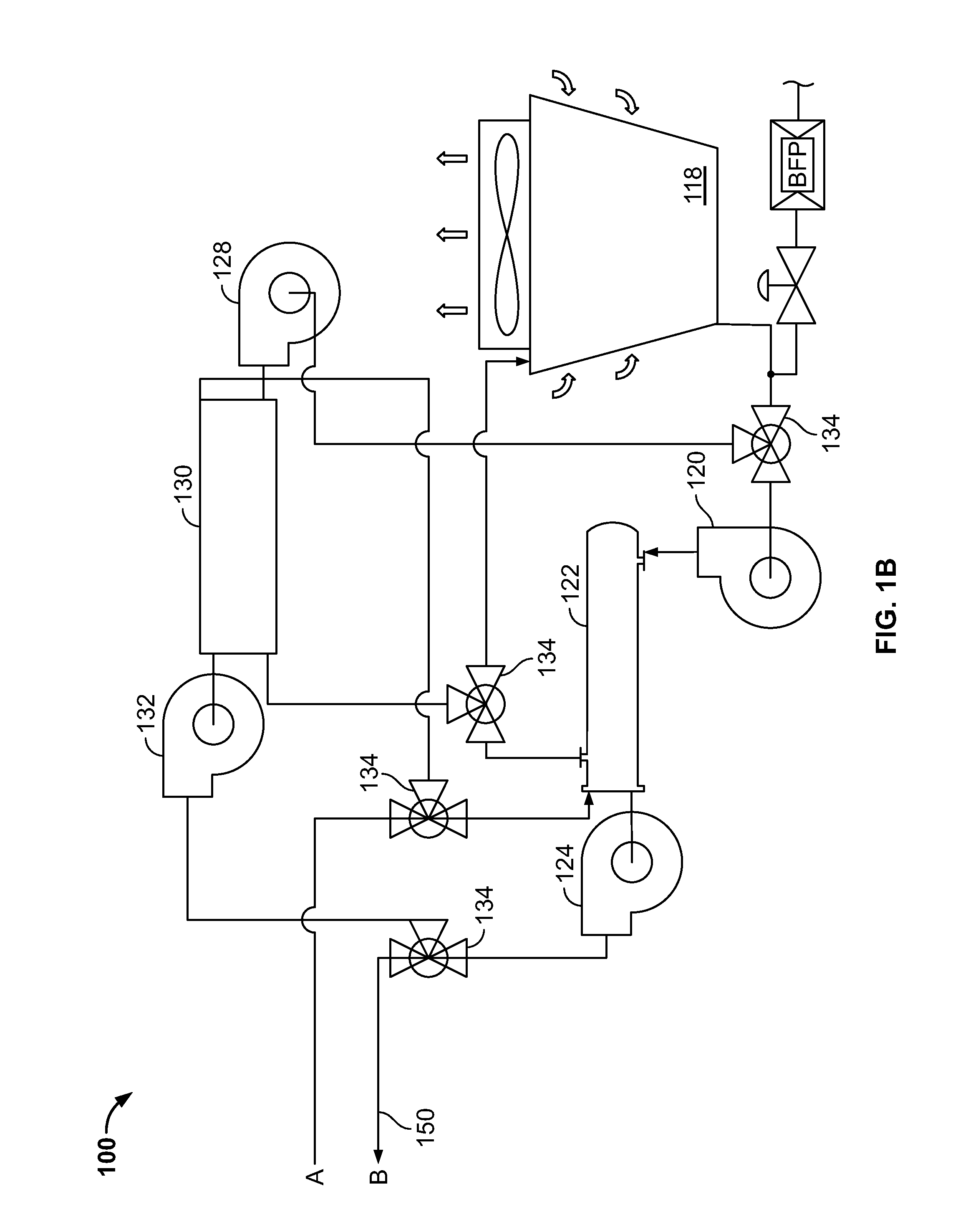
[0049]This disclosure relates to systems and methods for cooling a data center with an air handling system operable in two or more modes of operation. For instance, in some implementations, the air handling system may be operable in a first mode in which an outside airflow is circulated through a direct evaporative economizer module of the air handling system to cool the outside airflow. The cooled outside airflow is circulated to the data center to remove heat from the data center, such as, heat generated by computing devices operating in the data center. The air handling system may be operable in a second mode in which a return airflow is circulated through an indirect evaporative cooling module of the air handling system to cool the return airflow. The cooled return airflow is circulated to the data center to remove heat from the data center. The air handling system may switch from the first mode to the second mode based on, for instance, an unacceptable amount of contaminants de...


PUM


Abstract

Techniques for cooling a data center include operating an air handling system in a first mode of operation to provide an outside airflow cooled through a direct evaporative cooling module to a data center without substantial mixing of the cooled outside airflow with another airflow; determining that a measured outside air contaminant level exceeds a setpoint contaminant level; and based on the determination, operating the air handling system in a second mode of operation to provide a datacenter return airflow cooled through an indirect evaporative cooling module to the data center without substantial mixing of the cooled return airflow with another airflow.

Description

TECHNICAL BACKGROUND[0001]This disclosure relates to systems and methods for managing airflow to areas that contain electronic equipment, such as computer server rooms and server racks in computer data centers.BACKGROUND[0002]Computer users often focus on the speed of computer microprocessors (e.g., megahertz and gigahertz). Many forget that this speed often comes with a cost—higher power consumption. For one or two home PCs, this extra power may be negligible when compared to the cost to run the many other electrical appliances in a home. But in data center applications, where thousands of microprocessors may be operated, electrical power requirements can be very important.[0003]Power consumption is also, in effect, a double whammy. Not only must a data center operator pay for electricity to operate its many computers, but the operator must also pay to cool the computers. That is because, by simple laws of physics, all the power has to go somewhere, and that somewhere is, in the en...

Claims


Application Information

Patent Timeline
Patent Type & Authority Patents(United States)
IPC IPC(8): H05K7/20
CPCH05K7/20836H05K7/20745
Inventor MALONE, CHRISTOPHER G.SOMANI, ANKIT
Owner GOOGLE LLC
Learn More