Shoulder Forming Slip Form Die

A mold and road shoulder technology, which is applied in the field of road shoulder forming sliding molds, can solve the problems of non-standard functions of sliding molds, laborious and laborious shoulder forming, and low degree of automation, so as to reduce construction costs, reduce human labor, and have a high degree of automation Effect

Active Publication Date: 2019-09-03
云南穿山机甲能源装备科技有限公司
View PDF6 Cites 0 Cited by
  • Summary
  • Abstract
  • Description
  • Claims
  • Application Information

AI Technical Summary

Problems solved by technology

The existing road shoulder construction at home and abroad is mainly assisted by labor and machinery. The shoulder soil is transported to the site by dump truck and then leveled and formed by manual paving. This construction method is laborious and laborious. After leveling and forming, it needs to be compacted twice. The existing construction method has high cost and low construction efficiency.
[0003] In addition, there are also some refitting equipment of all kinds. The sliding mold used in the road shoulder forming equipment is not standardized and has a single function. The road shoulder sliding mold still has problems of low automation and incompatibility. Looking at the development of construction machinery at home and abroad, for road construction machinery, it is necessary to improve The degree of automation, reducing the labor intensity of workers, and improving construction quality are all its development requirements

Method used


Image

  • Shoulder Forming Slip Form Die
  • Shoulder Forming Slip Form Die
  • Shoulder Forming Slip Form Die

Examples


Embodiment 1

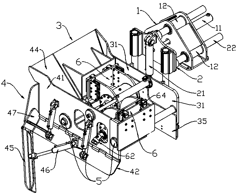
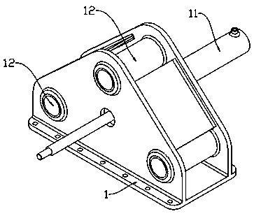
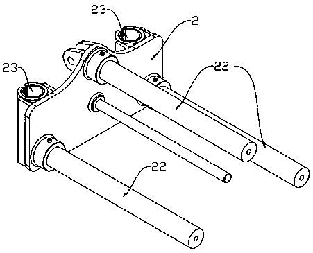
[0049] refer to Figure 1 to Figure 7 , the road shoulder forming slip form mold of the present embodiment includes a fixed seat 1, a general adjustment plate 2 connected to the fixed seat 1 and arranged vertically, and a mold connected to the general adjustment plate 2, and the mold includes two left and right mold units 3, 4;

[0050] Described left mold unit 3 comprises the left side plate 31 that is arranged vertically and the left guide plate 34 that is arranged on the front end of left side plate 31, and described right mold unit 4 includes the right side plate 41 that is arranged vertically and is arranged on the right side plate 41 front end and the right guide plate 44 that is arranged correspondingly with left guide plate 34;

[0051] The left and right mold units 3, 4 are slidably connected by a width adjustment unit 5 to move away from or approach each other in the horizontal direction. The width adjustment unit 5 includes a set of width adjustment cylinders 51 an...

Embodiment 2

[0061] refer to Figure 8 and Figure 9 The main difference between this embodiment and the above-mentioned embodiment 1 is that: the motor 62 of the left mold unit 3 in this embodiment is preferably connected to the support 621 arranged above the tamper 61 through a dovetail groove, and the left mold unit The motor 62 of the unit 3 and the tamper 61 are connected through a belt drive, so that the minimum width of the road shoulder can be further realized by such a design. The motor 62 of the right mold unit 4 is the same as that of Embodiment 1, that is, it is directly connected to its tamper 61 .

Embodiment 3

[0063] refer to Figure 10 to Figure 16 , the main difference between this embodiment and the above-mentioned embodiment 3 is: First, the tamping unit 6 in the present embodiment removes the guide rail 64, that is, the tamping device, so that the structure of the entire sliding form mold is more compact, and its total weight can be reduced, so that it can be directly The compaction function is realized by the general adjusting plate 2; secondly, the damping block 63 of the left mold unit 3 is evenly distributed on the side of the tamper 61 close to the left guide plate 34, and the damping block 63 of the right mold unit 4 63 are evenly distributed on the front and back sides of its tamp 61, that is, two are evenly distributed on each side, so as to improve the damping effect.


PUM


Abstract

The invention relates to a slip form mould for road shoulder forming. The slip form mould for road shoulder forming comprises a fixing seat, a general adjustment plate connected with the fixing seat and arranged vertically and a mould body connected with the general adjustment plate. The mould body comprises a left mould body unit and a right mould body unit, wherein the left mould body unit comprises a left side board arranged vertically and a left guide board arranged at the front end of the left side board, and the right mould body unit comprises a right side board arranged vertically and a right guide board arranged at the front end of the right side board and corresponding to the left guide board. The left mould body unit and the right body mould unit are connected in a sliding mode through a width adjustment unit to be away from or close to each other in the horizontal direction, a cylinder sleeve end of a width adjustment oil cylinder is fixed on the left side board, and a cylinder rod end of the width adjustment oil cylinder is fixed on the right side board. The slip form mould can adjust the width and thickness of the road shoulder and level out and pun the road shoulder according to the requirements.

Description

technical field [0001] The invention relates to the construction field of road construction machinery and equipment, in particular to a road shoulder forming sliding form mold equipped with road construction equipment. Background technique [0002] According to the construction situation of road construction projects in our country, the time left for road shoulder construction in the same period of road construction is generally very short, and the construction period is tight, so it is required that road shoulder construction should have a higher operating efficiency. The existing road shoulder construction at home and abroad is mainly assisted by labor and machinery. The shoulder soil is transported to the site by dump truck and then leveled and formed by manual paving. This construction method is laborious and laborious. After leveling and forming, it needs to be compacted twice. The existing construction method has high cost and low construction efficiency. [0003] In ...

Claims


Application Information

Patent Timeline
Patent Type & Authority Patents(China)
IPC IPC(8): E01C19/48
Inventor 陈建军
Owner 云南穿山机甲能源装备科技有限公司
Why Eureka
Try Eureka