A rolling seeding device

A seeding device and rolling technology, applied in the directions of seeding seeders, seeder parts, agricultural gas emission reduction, etc., can solve the problems of difficulty in realizing seeding demand, heavy labor burden, obstacles to automatic seeding, etc., and achieve the goal of promoting the development of automatic seeding, The effect of meeting sowing needs

Active Publication Date: 2022-05-17
宁波甬来信息科技有限公司
View PDF10 Cites 1 Cited by
  • Summary
  • Abstract
  • Description
  • Claims
  • Application Information

AI Technical Summary

Problems solved by technology

[0002] In the process of agricultural production, the cultivation of plants basically needs to be sown, and the sown seeds generally need to be buried in the soil. The traditional sowing process is done manually, which has low efficiency and heavy labor burden, which is not conducive to the development of agriculture. Therefore, improving Sowing efficiency and realizing sowing automation have become the focus of industry research
[0003] At present, the existing automatic seeding device adopts the structure of installing the seeding teeth on the roller during the sowing process. During the sowing process, the gravity of the device itself presses the seeding teeth down to realize the drilling operation of the seeding teeth. The direction in which the seeds are sent out is limited, resulting in a relatively fixed position of the seeding teeth, which makes it difficult to meet the sowing requirements of different sowing row spacings
In addition, during the sowing process, due to the different environments of the land, the soil in some places is hard or there are debris such as leaves, which makes it difficult for the sowing teeth to penetrate deep when the seeding teeth are punching holes, resulting in The holes for sowing are shallow, which is difficult to meet the needs of sowing, which hinders the implementation of automatic sowing

Method used


Image

  • A rolling seeding device
  • A rolling seeding device
  • A rolling seeding device

Examples


Embodiment Construction

[0025] In order to make it easy to understand the technical means, creative features, goals and effects achieved by the present invention, the following examples are combined with the appended figure 1 to attach image 3 The technical solutions provided by the present invention are described in detail, but the following content is not intended as a limitation of the present invention.

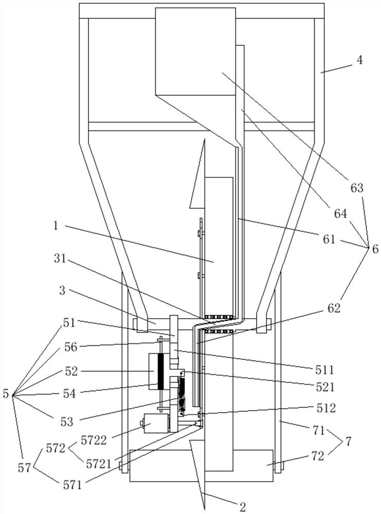
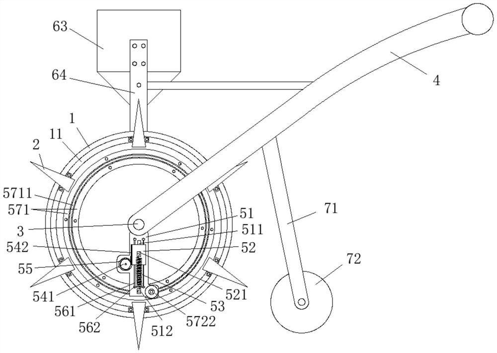
[0026] figure 1 It is a structural diagram of an angle of view of an embodiment of a rolling seeding device of the present invention; figure 2 It is a structural diagram of another perspective of an embodiment of a rolling seeding device of the present invention. Such as figure 1 with figure 2 As shown, the rolling seeding device provided in this embodiment includes: a roller 1 , a seeding tooth 2 , a central shaft 3 , a trolley frame 4 and an auxiliary impact mechanism 5 .

[0027] Specifically, one end of the hand push frame 4 is equipped with a central shaft 3 arranged horizontally, a...


PUM


Abstract

The invention provides a rolling sowing device, which belongs to the technical field of agricultural automation. A rolling type sowing device includes a roller, a seeding tooth, a central shaft, a trolley and an auxiliary impact mechanism; the present invention installs the sowing tooth by setting an installation track on one side of the roller mounted on the trolley through the central shaft, and realizes the The seeding teeth can be adjusted at any position on the installation track, and at the same time, the seed outlet is set on the central axis, which can always maintain the stability of the seed outlet position during the rotation of the roller, adapting to the sowing requirements of the seeding teeth at any position, and meeting the row spacing of different plants. Seeding requirements, at the same time, an auxiliary impact mechanism is installed on the central axis of the roller, so that the auxiliary impact mechanism can always maintain a vertical downward state, and it always acts on the bottom seeding tooth during the rotation of the roller to prevent the soil from being too hard The problem that the seeding teeth cannot go deep under such circumstances can better meet the needs of sowing and promote the development of agricultural automation.

Description

technical field [0001] The invention relates to the technical field of agricultural automation, in particular to a rolling sowing device. Background technique [0002] In the process of agricultural production, the cultivation of plants basically needs to be sown, and the sown seeds generally need to be buried in the soil. The traditional sowing process is done manually, which has low efficiency and heavy labor burden, which is not conducive to the development of agriculture. Therefore, improving Sowing efficiency and realizing sowing automation have become the focus of industry research. [0003] At present, the existing automatic seeding device adopts the structure of installing the seeding teeth on the roller during the sowing process. During the sowing process, the gravity of the device itself presses the seeding teeth down to realize the drilling operation of the seeding teeth. However, due to the The direction in which the seeds are sent out is limited, resulting in r...

Claims


Application Information

Patent Timeline
Patent Type & Authority Patents(China)
IPC IPC(8): A01C7/16A01C7/20
CPCA01C7/16A01C7/20Y02P60/20
Inventor 徐飞飞
Owner 宁波甬来信息科技有限公司
Why Eureka
Try Eureka