
Self-locking switch protection baffle and operation device thereof

A protective baffle and self-locking technology, which is applied in the direction of vertical pulling and isolation of switchgear, electric switch, air switch components, etc., can solve the problem of low work efficiency, easy dust and water accumulation in the protective cover, and easy falling off of the sheath and other issues to achieve the effect of saving working time, improving flexibility and improving work efficiency

Pending Publication Date: 2021-12-03
GUANGDONG SANSHUI INST OF HEFEI UNIV OF TECH +1
View PDF0 Cites 0 Cited by
  • Summary
  • Abstract
  • Description
  • Claims
  • Application Information

AI Technical Summary

Problems solved by technology

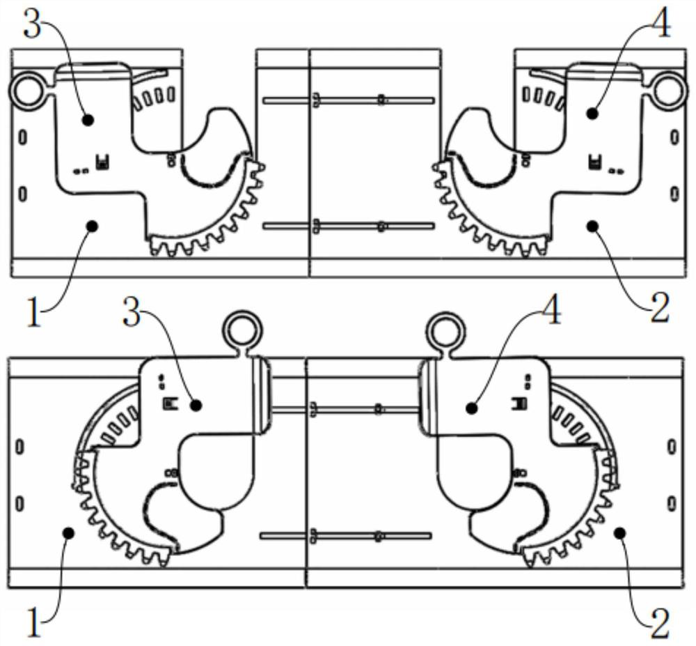
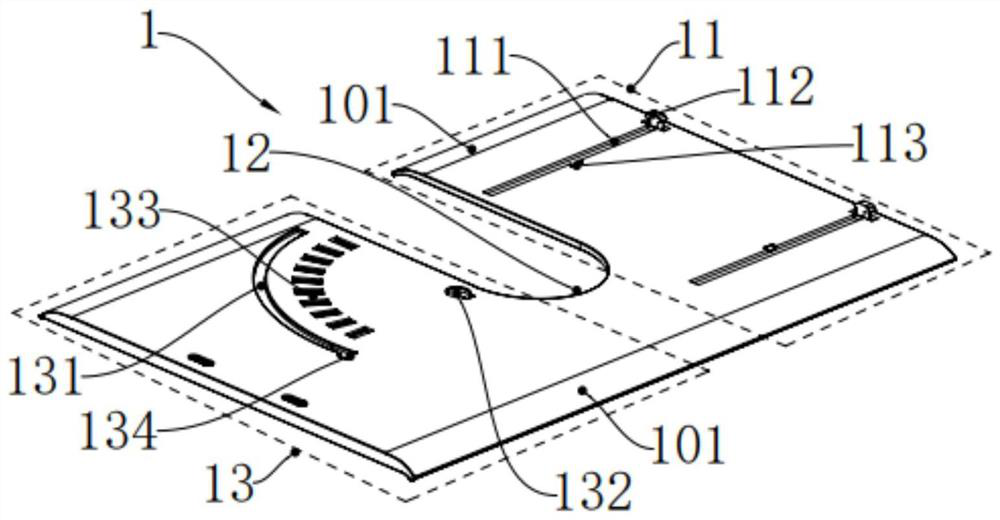
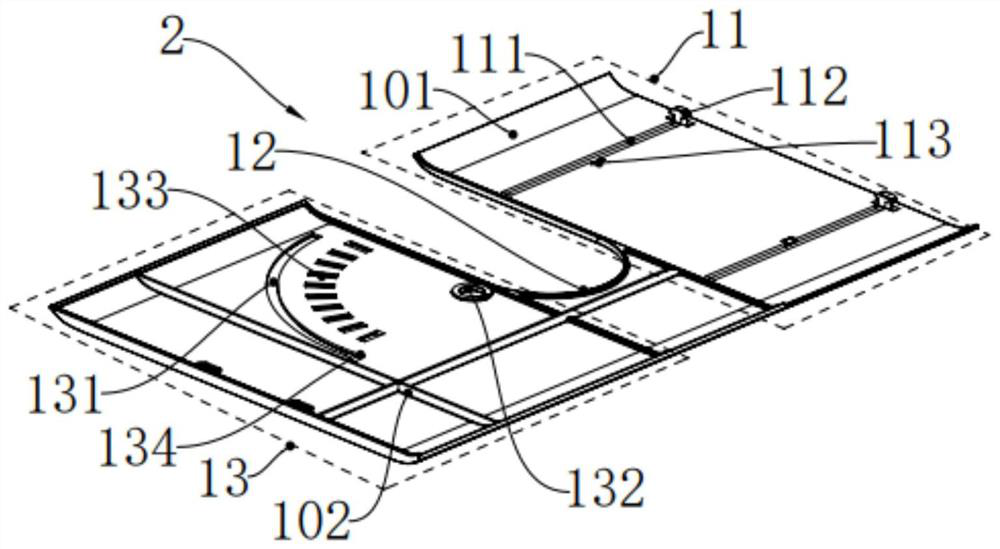
[0004] The purpose of the present invention is to propose a self-locking switch protective baffle to solve the problems of the traditional protective cover mentioned in the above background technology, such as easy accumulation of dust and water, easy falling off of the sheath, failure to measure temperature normally, etc., and provide multiple a way to seal the insulator;
[0005] In addition, the present invention also proposes an operating device for installing the above-mentioned self-locking switch protective baffle, so as to solve the problems of high installation cost and low work efficiency caused by the traditional protective cover mentioned in the above-mentioned background technology with the help of a live working vehicle , easy to operate, and wider range of application

Method used


Image

  • Self-locking switch protection baffle and operation device thereof
  • Self-locking switch protection baffle and operation device thereof
  • Self-locking switch protection baffle and operation device thereof

Examples


Embodiment Construction

[0040] The technical solutions of the present invention will be further described below in conjunction with the accompanying drawings and through specific implementation methods.

[0041] In describing the present invention, it should be understood that the terms "length", "width", "upper", "lower", "left", "right", "top", "bottom", "inner", " The orientation or positional relationship indicated by "outside", etc. is based on the orientation or positional relationship shown in the drawings, and is only for the convenience of describing the present invention and simplifying the description, rather than indicating or implying that the referred device or element must have a specific orientation, so as to Specific orientation configurations and operations, therefore, are not to be construed as limitations on the invention.

[0042] In addition, the terms "first" and "second" are used for descriptive purposes only, and cannot be interpreted as indicating or implying relative import...


PUM

PropertyMeasurementUnit
Radianaaaaaaaaaa

Abstract

The invention relates to the technical field of power equipment, in particular to a self-locking switch protection baffle which comprises a first sliding plate, a second sliding plate, a first rotating plate and a second rotating plate. The first rotating plate is provided with a closing part, a manual intervention part and a rotating transmission part, the closing part can rotate to an opening of the mounting notch of the first sliding plate along the guide of an arc-shaped sliding groove, and the manual intervention part and the rotating transmission part are distributed on the two sides of a rotating point of the first rotating plate; when external force acts on the manual intervention part or the rotating transmission part to enable the manual intervention part or the rotating transmission part to move, a sealing part follows and moves along the guide direction of the arc-shaped sliding groove. The second rotating plate and the first rotating plate are consistent in structure and are distributed in a mirror symmetry mode. The invention further relates to an operating device which can carry out hot-line work on the protection baffle. According to the invention, various insulator closing modes are provided, the operation is convenient, and the application range is wider.

Description

technical field [0001] The invention relates to the technical field of electric equipment, in particular to a self-locking switch protection baffle and an operating device thereof. Background technique [0002] According to the requirements in the "Southern Power Grid Main Transformer Installation Operation Guide" and "Southern Power Grid Engineering Construction Process Control Specifications", in the construction of 10kv distribution network projects, the exposed electrical parts must be insulated to ensure maintenance personnel The operation is safe, and at the same time, it prevents animals from climbing to the exposed parts of electricity and causing short circuits and causing failures. [0003] At present, high-voltage isolation switches and other equipment are commonly used in 10KV distribution networks. The traditional protective cover is made of rubber, which is not only easy to accumulate dust and water, easy to fall off, and unable to measure temperature normally,...

Claims


Application Information

Patent Timeline
IPC IPC(8): H01H31/02H01H9/02H02B11/20
CPCH01H31/02H01H9/02H01H9/0264H02B11/20
Inventor 陈潇跃何志艺杨国宇何燕君
Owner GUANGDONG SANSHUI INST OF HEFEI UNIV OF TECH
Learn More