Case and board card fixing baffle thereof
A technology for fixing baffles and boards, applied in the fields of climate sustainability, instrumentation, computing, etc., can solve the problems of prolonged test time, waste of customer costs, cumbersome replacement process operation, etc., to shorten the test time and reduce procurement costs. Effect
- Summary
- Abstract
- Description
- Claims
- Application Information
AI Technical Summary
Problems solved by technology
Method used
Image
Examples
Embodiment 1
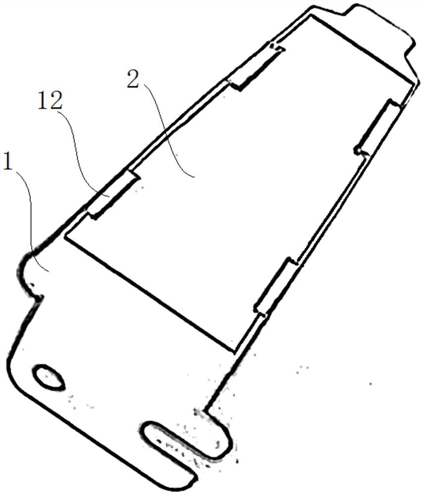
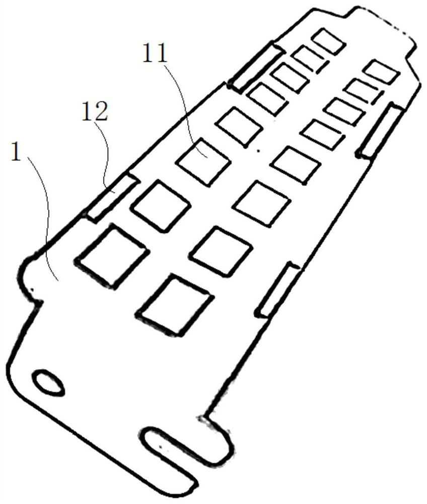
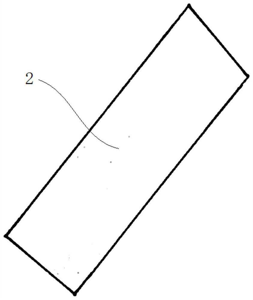
[0040] In this embodiment, the length of the baffle body 1 is 100 mm, and the width is 14 mm. The connecting portion has four insertion slots 12, the insertion slots 12 are close to the length side of the ventilation area, and two insertion slots 12 are provided on both sides of the ventilation area. The distance between the insertion slot 12 and the side edge of the end of the baffle body 1 at the end where the insertion slot 12 is located is 20 mm. The length of the insertion slot 12 is 10 mm, the width is 3 mm, and the width of the groove formed between the insertion slot 12 and the baffle body 1 is 1.5 mm. The baffle body 1 is cast and formed at one time using a mold. The user can also set the number, size and distribution of the insertion slots 12 according to the needs. For example, three insertion slots 12 can be arranged on both sides of the ventilation area, and one insertion slot 12 can be arranged at the midpoint of the ventilation area. The corresponding position...
Embodiment 2
[0045] In this embodiment, the dimensions of the baffle body 1 and the baffle plate 2 may refer to the first embodiment. The connecting part is two insertion slots 12, and the insertion slots 12 are close to the width side of the ventilation area. Both ends of the ventilation area are provided with an insertion slot 12 , and the insertion slot 12 is 10 mm away from the side edge of the end of the baffle body 1 at the end where the insertion slot 12 is located. The length of the insertion slot 12 is 6 mm, the width is 3 mm, and the width of the groove formed between the insertion slot 12 and the baffle body 1 is 1.5 mm. The shielding plate 2 is inserted from one side of the baffle body 1 along its width direction. This side is provided with two anti-falling protrusion structures, and the other side of the shielding plate 2 is provided with two limiting grooves. For the structure, refer to the insertion slot 12 in the first embodiment. The escape groove is located in the middl...
Embodiment 3
[0049] In this embodiment, the dimensions of the baffle body 1 and the baffle plate 2 may refer to the first embodiment. The connecting parts are 5 fixing cards, the fixing cards include the connecting pieces of the vertical baffle body 1 and the fixing protrusions extending toward the ventilation area. The distance decreases and increases. The length of the lower end of the fixed protrusion is 2-3 mm, and the distance between the lower end of the fixed protrusion and the baffle body 1 is 1.5 mm.
[0050] One end of the baffle body 1 is provided with a fixing card, the fixing card is 10mm away from the side edge of the end of the baffle body 1 at the end where the fixing card is located, and the other end is provided with a protruding structure to prevent falling off. Two fixing cards are provided on both sides of the baffle body 1, and the fixing cards are 20 mm apart from the side edge of the end of the baffle body 1 at the end where the fixing cards are located. During th...
PUM
| Property | Measurement | Unit |
|---|---|---|
| Length | aaaaa | aaaaa |
Abstract
Description
Claims
Application Information
 - R&D
- Intellectual Property
- Life Sciences
- Materials
- Tech Scout
- Unparalleled Data Quality
- Higher Quality Content
- 60% Fewer Hallucinations
Browse by: Latest US Patents, China's latest patents, Technical Efficacy Thesaurus, Application Domain, Technology Topic, Popular Technical Reports.
© 2025 PatSnap. All rights reserved.Legal|Privacy policy|Modern Slavery Act Transparency Statement|Sitemap|About US| Contact US: help@patsnap.com


