
Image prediction method, coder, decoder, and storage medium

A prediction method and encoder technology, applied in the field of video coding and decoding, can solve problems such as incomplete consideration and low prediction efficiency, and achieve the effects of improving prediction efficiency, small prediction residual error, and low bit rate

Active Publication Date: 2021-12-10
GUANGDONG OPPO MOBILE TELECOMM CORP LTD
View PDF16 Cites 0 Cited by
  • Summary
  • Abstract
  • Description
  • Claims
  • Application Information

AI Technical Summary

Problems solved by technology

However, when performing component prediction, the existing cross-component prediction technology does not consider comprehensively, resulting in low prediction efficiency

Method used


Image

  • Image prediction method, coder, decoder, and storage medium
  • Image prediction method, coder, decoder, and storage medium
  • Image prediction method, coder, decoder, and storage medium

Examples


Embodiment Construction

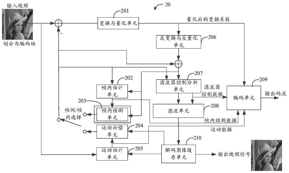
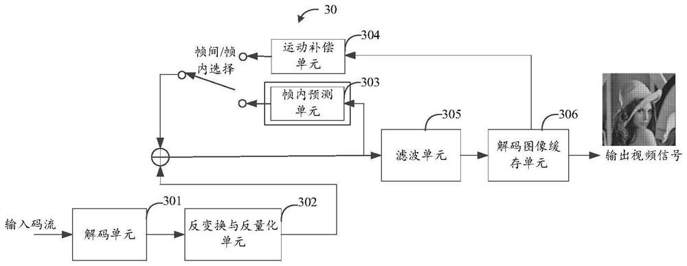
[0032] In order to understand the characteristics and technical contents of the embodiments of the present application in more detail, the implementation of the embodiments of the present application will be described in detail below in conjunction with the accompanying drawings. The attached drawings are only for reference and description, and are not intended to limit the embodiments of the present application.

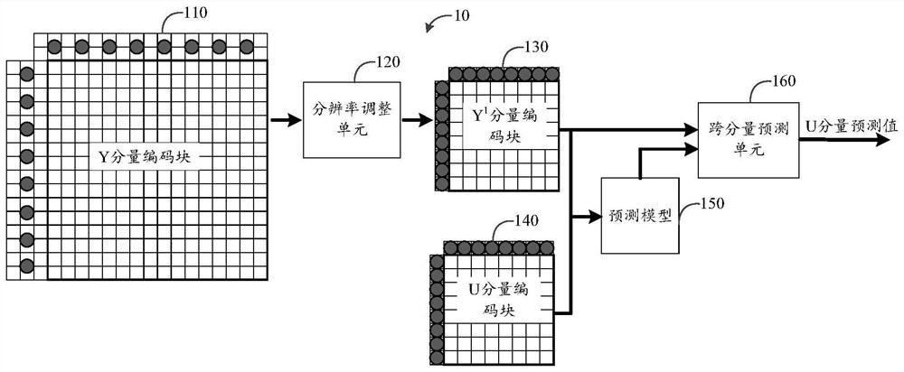
[0033] In a video image, the first image component, the second image component and the third image component are generally used to represent the coding block; where these three image components are a luminance component, a blue chrominance component and a red chrominance component respectively , Specifically, the luminance component is usually represented by the symbol Y, the blue chrominance component is usually represented by the symbol Cb or U, and the red chrominance component is usually represented by the symbol Cr or V; thus, the video image can be represented b...


PUM


Abstract

Disclosed are an image prediction method, a coder, a decoder, and a storage medium. The method comprises: obtaining an initial prediction value of an image component to be predicted of the current block in an image by means of a prediction model; and filtering the initial prediction value to obtain a target prediction value of said image component of the current block.

Description

technical field [0001] The embodiments of the present application relate to the technical field of video coding and decoding, and in particular, to an image prediction method, an encoder, a decoder, and a storage medium. Background technique [0002] In the latest video coding standard H.266 / Versatile Video Coding (VVC), the existence of cross-component prediction has been allowed; among them, cross-component linear model prediction (Cross-component LinearModel Prediction, CCLM) is a typical One of the cross-component prediction techniques. Using cross-component prediction technology, it is possible to predict another component (or its residual) from one component, such as predicting a chroma component from a luminance component, or predicting a luminance component from a chroma component, or predicting a chroma component from a chroma component, etc. . [0003] Different components have different statistical properties, so that there are differences in the statistical pro...

Claims


Application Information

Patent Timeline
Patent Type & Authority Applications(China)
IPC IPC(8): H04N19/149H04N19/80
CPCH04N19/80H04N19/50H04N19/42H04N19/176H04N19/186H04N19/117H04N19/593H04N19/105H04N19/82H04N19/124
Inventor 万帅霍俊彦马彦卓张伟
Owner GUANGDONG OPPO MOBILE TELECOMM CORP LTD
Learn More