Intelligent wardrobe and management method thereof
A kind of wardrobe and intelligent technology, which is applied in the direction of wardrobe, cupboard, electric digital data processing, etc., can solve the problem of spending a lot of time, and achieve the effect of improving the efficiency of clothes search and shortening the time
Pending Publication Date: 2021-12-17
HAIER IOC ECOSYSTEM TECH (SHANGHAI) CO LTD +1
0 Cites 0 Cited by
AI-Extracted Technical Summary
Problems solved by technology
[0003] With the continuous improvement of people's living standards, the types and quantities of clothes of users are also increasing. Correspondingly, more and more clothes are stored i...
Method used
[0093] The structure body 42 is concealed and installed in the rod body 41, which can protect the clothing positioning module and related circuits, and can play the role of improving the bending strength of the hanging rod 40 at the same time.
[0097] The reed switch 431, also known as a reed switch (Reed Switch), is an electric switch that controls the working state by applying a magnetic field. The magnetic reed switch seals two magnetic reeds (usually composed of two metals, iron and nickel) in a glass tube. The two magnetic reeds are overlapped but there is a small gap in the middle. The contacts are plated with a very hard metal (usually rhodium and ruthenium) to increase the life of the switching times. The glass tube is usually injected with nitrogen or some equivalent inert gas, or the inside of the glass tube is made into a vacuum state.
[0124] Thereby, by controlling the operating state of the power supply module through the sensor module, the effect of "energizing when someone is on, and when no one is powering off" is realized, and the safety of the smart wardrobe is improved.
[0143] Optionally, the camera can use an infrared camera, so that the camera can complete image acquisition without depending on brightness when shooting. At the same time, in infrared imaging, due to the obvious features of human limbs, it is easy to be eliminated and corrected by neural n...
Abstract
The invention provides an intelligent wardrobe and a management method thereof. The intelligent wardrobe is provided with a main control module and an image recognition module, wherein the image recognition module can recognize and obtain image information of clothes placed by a user and send the image information to the main control module; and the main control module can further obtain position information of the stored clothes and store the image information, the position information and the attribute information of the clothes according to corresponding relations. When the user initiates a clothes position query request, the main control module can determine target position information corresponding to target attribute information according to the target attribute information of target clothes in the clothes position query request and the corresponding relation of currently stored image information, position information and attribute information, and outputs corresponding position prompt information; and therefore, the user can quickly position the target clothes according to the prompt information, so the time of searching the target clothes by the user can be greatly shortened, and clothes searching efficiency is improved.
Application Domain
WardrobesDigital data information retrieval +3
Technology Topic
EngineeringImage identification +1
Image
Examples
- Experimental program(1)
Example Embodiment
[0060] In order to make the objects, technical solutions, and advantages of the present invention more clearly, the technical solutions in the embodiments of the present invention will be described in contemplation in the embodiment of the present invention. It is an embodiment of the invention, not all of the embodiments. Based on the embodiments in the present invention, all other embodiments obtained without creative labor are not made in the premise of creative labor.
[0061] The terms used in the present application examples are only for the purpose of describing particular embodiments, not intended to limit the invention. The "one" and "one" "one" and "" "" used in the present application embodiment are also intended to include most forms unless the context clearly represents other meanings.
[0062] It will also be noted that the term "comprising", "comprising" or any other variable is intended to cover non-exclusive contained contained, so that a product or system including a series of elements includes not only those elements, but also not expressly listed. Other elements or elements that are also inherent to this item or system. In the absence of more restrictions, the elements defined by the statement "include a ...", and there is no elimination in the goods including the elements, there are additional elements.
[0063] Wardrobe is a common furniture. In the prior art, when the number of clothings stored in the wardrobe is more, if the user needs to find a particular cloth, the user may need a one-piece to replay, resulting in Time spent, low processing efficiency.
[0064] The smart wardrobe and its management methods provided herein are intended to address prior art issues.
[0065] The main idea of this application is: Based on intelligent home technology, this application proposes a smart wardrobe with a master module and an image identification module, wherein the image recognition module can identify image information of the clothing placed, and transmitted. The main control module, the main control module can also obtain the location information of the clothes, and save the image information, attribute information and location information in accordance with the correspondence. When the user initiates a laundry position query request, the master module can determine the target location information of the target laundry that the user queries, and outputs the corresponding location prompt information, so that the user can quickly locate the target laundry according to the prompt information. It can greatly shorten the time to find the target laundry and improve the availability of the clothes.
[0066] The following technical solutions will be described in detail below with specific embodiments of the technical solutions of the present application and how the technical solutions of the present application will be described in detail. The following specific embodiments may be combined with each other, and will not be described in some embodiments for the same or similar concepts or processes. The embodiments of the present application will be described below with reference to the drawings.
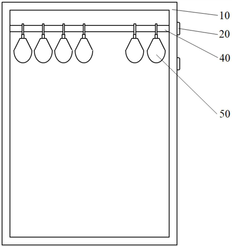
[0067] In some embodiments, a smart wardrobe is provided. figure 1 A schematic of a smart wardrobe provided by the embodiment of the present application, such as figure 1 As shown, the smart wardrobe includes: the cabinet body 10, the main control module 20 and the image recognition module 31 (not shown) of the cabinet body 10, is disposed inside the cabinet 10 and the lane 40 of the hanger 50;
[0068] Wherein the hanging lever 40 can be a top position provided in the interior space of the cabinet 10, the housing 40 can be disposed in a vertical structure, and the cross section of the lane 40 may be circular, or other shapes such as squares, such as squares. The hanger 50 can be suspended on the lane 40.
[0069] Among them, the cabinet includes a first cabinet door and a second cabinet gate;
[0070] The image recognition module is disposed at the first cabinet door and the second cabinet door for acquiring the laundry when the user is suspended on the hanger through the hanger through the hanger. Image information, and transmitting the image information to the main control module;
[0071] refer to figure 1 The master module 20 is configured to acquire the position information of the hanger 50 on the hanging rod 40, and corresponding to the corresponding relationship of the image information and the attribute information, the main relationship is corresponding to the corresponding relationship of the attribute information. save;
[0072] Wherein, the attribute information is obtained for the laundry to obtain the smart wardrobe for the smart wardrobe; for example, when the user places the new cloth into the smart wardrobe, the attribute information of the laundry can be entered through the associated app on the terminal, and the clothing The attribute information and image information are pre-saved in accordance with the correspondence.
[0073] Among them, one end of the housing 40 can be electrically connected to the master module 20 such that the main control module 20 can accurately obtain the location information of the laundry.
[0074] Further, the master module 20 is also configured to determine the target property information of the target laundry in the clothing position query request, and the corresponding relationship of the currently saved image information, location information, and attribute information, according to the corresponding relationship of the currently saved image information, location information, and attribute information. The target location information corresponds to the target property information, and outputs the corresponding position prompt information.
[0075] Specifically, the user can communicate with the master module 20 through the user terminal, and transmit the laundry position query request to the master module 20 through the user terminal.
[0076] In addition, the master module 20 may also be provided with a speech recognition module, and the user can directly carry out the laundry position query by the speech command. Accordingly, the main control module 20 analyzes the user's voice command to obtain the laundry position. Query request.
[0077] Correspondingly, the smart wardrobe can be provided with a voice broadcast module and / or a display module, or a smart closet can also communicate with an external device such as a smart speaker, a smart display, and the master module 20 can pass the voice block module and / or display. The module, or, the corresponding position prompt information is output by the above external device.
[0078] Optionally, the main control module can also obtain the storage time node of the laundry, saving the storage time node of the laundry with the corresponding image information, attribute information, location information, and statistics on the storage of the clothes, and passed The user terminal is displayed to the user.
[0079] Alternatively, the main control module can also be placed in the wardrobe in the wardrobe according to the storage time node of each of the clothes, and the storage of each garment is stored in the wardrobe, and is sorted, and the time is stored The longest one or more clothes, the longest time of storage of the one or more clothes, indicating that the user uses the smaller frequency, thereby, and the main control module can propose recommendations to the user, for example, " XX clothing has not been used by XX, it is recommended to eliminate "etc."
[0080] Alternatively, the main control module can also put the first time the time stored in the wardrobe as the purchase time of the laundry, and statistics on the use of the clothing and display it to the user.
[0081] This embodiment provides a smart wardrobe, which is provided with a master module and an image recognition module, wherein the image recognition module can identify the image information of the clothing placed, and transmitted to the master module, the main control module is OK. Gets the location information of the clothing, and saves the image information, location information, and attribute information of the clothing in accordance with the correspondence. When the user initiates a clothing position query request, the master module determines the target attribute information corresponding to the target property of the target cloth in the laundry position query request, and the corresponding relationship of the currently saved image information, location information, and attribute information. The location information, and outputs the corresponding location prompt information, and the user can quickly locate the target laundry according to the prompt information, so that the user can significantly shorten the time of the target laundry and improve the clothing search efficiency.
[0082] In some embodiments, the image information includes: color information, texture information, outline information, pocket feature information, lead feature information, cuff feature information, button feature information, and one of the zipper feature information or at least two.
[0083] Specifically, in the image information, the core parameters include: color, texture, outline, pocket position, neck port, cuff, etc., and pocket shape, button, buttons, two sides and zipper, zipper sides, etc. Extraction, as a secondary core parameters, only the core parameters cannot be adjusted to determine the laundry, the non-core parameters need to be adjusted as the alignment. And the hanger, clothespin, etc. are completely no unchecked parameters. That is to say, the clothing information is completely independent of the mounting tool.
[0084] Thus, based on the above image information, the laundry recognition can be avoided, and the pocket is pulled out, the zipper is not pulled or the button is not systematically identified, and the misleading when replacing the mount tool is avoided.
[0085] In some embodiments, the attribute information comprises: role information, type information, color information, applicable season information, applicable weather information, applicable occasion information, texture information, material information, size information, washing mode information, washing temperature information Any one or at least two items.
[0086] Where the role information indicates the use of user identities corresponding to the clothing; the type information represents the type of clothing; color information indicates the color of the clothing; applicable season information, applicable weather information, applicable occasion information, respectively, to use the clothing season, weather, and occasion; texture The information indicates the texture characteristics of the clothing; the material information represents the material characteristics of the laundry; the size information indicates the size feature of the laundry; the washing mode information, the washing temperature information indicates a suitable method of washing the laundry and water temperature.
[0087] Thus, based on the above attribute information, the corresponding laundry can be uniquely determined, so that the user can find the corresponding laundry based on the attribute information.
[0088] In some embodiments, the specific structure of the hanging rod 40 and the hanger 50 will be explained.
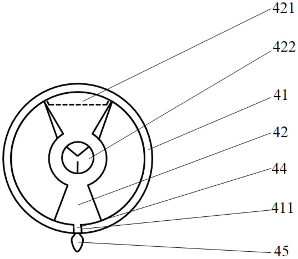
[0089]figure 2 The cross-sectional view of the lane 40 in the present application embodiment, such as figure 2 As shown, the lane 40 includes a rod body 41, a structural body 42 disposed inside the rod body 41;
[0090] Among them, the rod body 41 is made of non-conducting material, such as aluminum tubes, 304 stainless steel pipes, polytetrafluoroethylene tubes (with reduced effects, facilitating the hanger on moving), etc., the rod body 41 mainly carries the carrier 50 and facilitates the hanger 50 left and right movements;
[0091] The rod body 41 can be set to figure 2 The displayed cross section is a circular circular tube structure, or may be a structure provided as a cross section of other shapes (e.g., rectangles, triangles, trapezoids, etc.), which is not limited thereto.
[0092] refer to figure 2 The structural body 42 includes a mounting groove 421 for mounting the laundry positioning module and a central aperture 422 for the trace; wherein the laundry positioning module can position the hanger 50 of the laundry, the main control module 20 passes through the laundry positioning module. Gets the location information of the hanger 50 in the laundry on the lane 40.
[0093] Structural 42 hide mounted in the rod body 41, protect the laundry positioning module and related circuitry, while capable of improving the bending strength of the lane 40.
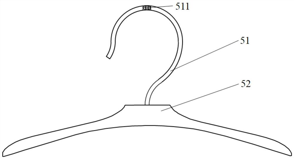
[0094] image 3 A schematic diagram of the hanger 50 in the embodiment of the present application, such as image 3 As shown, the hanger 50 includes hooks 51 and a straw 52, and the hook 51 is provided with a hook magnet 511 with the contact position of the rod body 41; the hook magnet 511 is used to assist the laundry positioning module.
[0095] The specific structure and working principle of the laundry positioning module are explained below.
[0096] Figure 4A A schematic diagram of the clothing positioning module in the present application example, Figure 4b A schematic diagram of another perspective of the clothing positioning module in the present application embodiment, Figure 4C A schematic diagram of a single laundry positioning module in the present application embodiment, such as Figure 4A-Figure 4C As shown, the laundry positioning module includes: a plurality of regeneus 431;
[0097] The reed 431, also known as the reed switch, is an electric switch to control the working state by applying a magnetic field. The reed switch is to seal the two magnetic reeds (usually composed of two metals of iron and nickel) in the glass tube, and the two magnetic rings are overlapped but the intermediate interval has a small void, two magnetic reed The contacts are plated with a very hard metal (usually ruthenium and ruthenium) to enhance the life of the switching. Nitrogen or some equal inert gases are typically injected into the glass tube, or in the inside of the glass tube into a vacuum state.
[0098] The function of the magnetic spring is equivalent to a magnetic flux conductor, and when there is no magnetic field outside, the two magnetic rings do not contact; when the magnetic field is generated by a permanent magnet or a magnetic coil, the external magnetic field has a two-piece magnetic spring end point position. Different poles are produced, and when the magnetic force exceeds the elastic force of the magnetic spring sheet itself, the two magnetic rings can absorb the conductive circuit; when the magnetic field weakens or disappears, the magnetic spring sheet is released, and the contact surface is released. It will be separated so that the circuit is disconnected.
[0099] In this embodiment, the plurality of reed 431 are disposed within the mounting groove 421, each of which is fixed, provided with a corresponding identifier (eg, numbered, etc.), and has a separate lead connection master. When the user is hung on the hook magnet 511 in the hanger 50, the user is hovering the hook magnet 511 in the hanger 50, the magnetic field generated by the hook 511 causes a reed from the contact position of the hook 51 and the rod 41. 431 The corresponding circuit is turned on, the main control module 20 can know which particular identified reed 431 appears above the hook magnet 511, that is, the laundry is hung, thereby, the main control module 20 passes through multiple regenesis 431 The working state of the corresponding circuit acquires the position information of the hanger 50 on the laundry 40.
[0100] It will be appreciated that the number of the reed 431 can be increased in the case where the launder interior cloth is placed, and the reed 431 may be equal spacing between the reed 431, or is a non-equidistant setting.
[0101] In some embodiments, reference Figure 4A-Figure 4C In order to prevent the hook magnet 511 of a hanger 50 from causing a circuit conduction of the plurality of regeneus 431, the laundry positioning module further includes: a plurality of magnetic structures 432;
[0102] Among them, the magnetic structural body 432 is provided with a cavity for accommodating the reed 431, an opening of the cavity faces above the rod body 41. Each of the reeds 431 is provided in a specialized slimming structure 432, in order to prevent the non-positive magnets from malfunction, the cavity in the middle of the magnetic structure 432 can be designed to be deeper, the reed tube The 431 placement is also deeper, and avoids the trigger of the hook magnet 511 in the non-positive side of the non-positive.
[0103] For example, Figure 4C In the middle, it is defined that the height of the sound magnetic structure 432 is H2, the width is L, the relationship between the two can be set to H2 ≥ 4L, thereby ensuring that the cavity is deep enough.
[0104] Thus, by providing the magnetic structural body 432 to ensure that each of the reed 431 can only be triggered by the hook magnet 511 directly above, it ensures that the master module 20 can accurately obtain the position information of the hanger 50.
[0105] It will be appreciated that the width of the hook magnet 511 should be less than or equal to the opening width of the cavity of the magnetic structural body 432 to ensure that the single hook magnet 511 changes only by the operating state of the reed 431 inside the single diaphragm structure 432.
[0106] In some embodiments, reference Figure 4A-Figure 4C Since the two side walls of the cavity of the sound magnetic structure 432 have a certain thickness, in order to prevent the position of the hook magnet 511 from being in the two reed 431, that is, the side wall located adjacent two magnetic structural body 432. At this time, the hook magnet 511 may not be triggered, and in order to solve this problem, in this embodiment, the laundry positioning module further includes: lane magnet 433;
[0107] Among them, each of the sides of the stem 432 extends in the direction of the rod body 41, and the polarity of the hook magnet 433 facing the hook 511 is the same as the polarity of the hook magnet 511 to the reed 431.
[0108] Specific, reference Figure 4C At both sides of each of the magnetic structures 432, a tight lamin magnet 433 is provided, which is shielded by the susceptible structural body 432, and the reed 431 in the magnetic structure 432 is not triggered. The same side polarity (i.e., the polarity facing the hook 51) is the same, and the polarity of the hook magnet 511 (i.e., the polarity of the reed 431) and the lane magnet 433. The upward side is the same, so that when the user just places the hanger 50 of the hanging laundry in the middle of the two reed 431, it is said that the hinge magnet 433 is placed, due to magnetic The instability of repulsiveness (unless the magnetic is small, it is difficult to stabilize), it will slide quickly to both sides, affected by another magnetifier force, which will fall in a balanced place, that is, one The reach 431 is directly above, thereby ensuring that a hanger 50 triggers a reed 431, and ensures that a hanger 50 can trigger a reed 431.
[0109] Alternatively, the height of the lane magnet 433 may be a height below the magnetic structure 432 to ensure that the lane magnet 433 does not affect the reed 431 inside the magnetic structural body 432. For example, Figure 4C In the middle, the height of the magnetic structure 432 is defined is H2, and the height of the lane magnet 433 is defined is H1, then the relationship between the two can be set to H2> H1.
[0110] In some embodiments, the laundry positioning module includes: a plurality of reed, a plurality of magnetic structures, and a lane magnet; wherein each of the reed tubes is provided with a magnetic structure in both sides in the rod extension direction; The sound magnetic structure is provided with a cavity for receiving the lane magnet, and the opening of the cavity faces above the rod.
[0111] Figure 4D Another illustration of a single laundry positioning module in the present application example, such as Figure 4D As shown, it is also possible to set the housing magnet 433 inside the cavity of the magnetic structural body 432, and then a reed 431 is provided between the two magnetic structures 432, thereby ensuring that a hanger 50 triggers one The reed tube 431 and ensures that a hanger 50 can trigger a reed 431.
[0112] In some embodiments, the master module 20 is further configured to change the working state of the circuit in accordance with the circuit of the plurality of regeneus 431 in the suspension position of the laundry, acquire the hanger 50 in the lane 40 in the lane 40. Location change information, and updates the image information, attribute information, and location information of the clothing according to the location change information.
[0113] For example, if the user hungs the laundry on the leftmost first hanger 50, at this time, the hook magnet 511 of the hanger 50 causes the leftmost first reed 431 to be turned on, so that the reed tube 431 The corresponding circuit is turned on, the main control module 20 performs the image information of the laundry, and the attribute information corresponds to the binding of the corresponding relationship, and saves.
[0114] When the suspension position of the laundry changes, the user adjusts the position of the hanger 50, for example, sliding the hanger 50 along the hinge 40 to the right of the three hanger 50, at this time, the hanger 50 will make the most during the sliding process. The first reed 431, the leftmost second reed 431, the leftmost third reed 431, the leftmost fourth reed 431 is turned on, and only only The leftmost fourth reed 431 maintains the state of continuously conducting, and the main control module 20 determines the final left side according to the working state of the circuit corresponding to the four reed 431. The position, thus resets the image information of the clothing, the attribute information, with the leftmost fourth position, and re-saved, thereby completing the update of the laundry storage location information.
[0115] In some embodiments, reference figure 2 A pass groove 411 is provided below the rod body 41, and the structural body 42 further includes a restricted convex structure 44 disposed at the pass groove 411. The limit convex structure 44 is used to prevent the structural body 42 from rotating in the rod body 41, thereby avoiding the position of the reed 431 to change the position of the hook magnet 511. At the same time, it is also convenient to reduce the assembly difficulty when the rod body 41 is assembled with the structural 42.
[0116] In some embodiments, reference figure 2 The structural body 42 also includes a position indicator 45 corresponding to the reed tube 431; the position indicator 45 is drawn by the pass groove 411; the master module 20 is turned on by the control position indicator 45 to output location prompt information.
[0117] For example, if the master module 20 determines that the target laundry in the laundry position query is hung by the position of the first reed 431 on the rightmost side, the first position indicator 45 on the rightmost side can be controlled or flashed. It is thus a prompt user.
[0118] In some embodiments, for the center hole 422, the interior space is a trace channel, which is avoided to contact with the metal rod. Alternatively, the metal rod body 41 can be utilized as a ground, as a common circuit circuit of the reed 431 and the indicator, so that these wiring circuits need only one wire.
[0119]Providing the central bore 422 of the outer wall 42 and connected to the vertical support structure, the outer wall is provided with holes, 431 and so the reed wires through PWRLED.
[0120] In some embodiments, the power module further comprising a smart wardrobe ( figure 1 Not shown), the power supply module provides power to each module for the smart wardrobe needs electricity, so that each module can work properly.
[0121] Alternatively, the sensor module further includes a intelligent wardrobe for controlling the operation state of the power module.
[0122] Wherein the sensor module may detect a distance between the user and the smart wardrobe, upon detecting a user with the smart closet distance less than or equal predetermined distance, then the user near the wardrobe described, the sensor module controls the power supply module is switched on, so that the smart each module to work wardrobe; upon detecting a distance between the user and the smart wardrobe is greater than a predetermined distance, away from the user wardrobe case described, the sensor module controls the power supply module is turned off, so that each module smart wardrobe stopped.
[0123] Optionally, the sensor module may be used to detect opening of the door of the closet and the intelligent closed state, the smart detection closet doors in an open state, indicating that the user is using wardrobe case, the sensor module controls the power supply module is switched on, so that the smart each module to work wardrobe; upon detection of the intelligent wardrobe doors in the closed state, then the user is not using the wardrobe described, the sensor module controls the power supply module is turned off, so that each module smart wardrobe stopped.
[0124] Thus, by controlling the power supply module operating state of the sensor module, "it was energized, no power-off" effect, improve the security of smart wardrobe.
[0125] In some embodiments, the smart wardrobe further comprising: a server ( figure 1 Not shown), the main control module 20 for laundry corresponding to the image information, the attribute information storage time (for example, storage time of the node, storage duration, etc.) and the position information to the server for storage; server for receiving the user after the interactive command terminal, content interaction instruction corresponding feedback information to the user terminal.
[0126] Wherein, for example, may be a laundry interaction instruction location query command, display command information closet clothing and the like.
[0127] Thus, the user can query remote user terminal, and the communication between the server via a smart wardrobe, clothes can ensure consistent data within the data with the intelligent terminal queries the user wardrobe, guarantee real-time data;
[0128] Further, even if the respective modules in the power off state of the smart closet (e.g., when the user is not near the wardrobe intelligent power module is turned off), the user positions the laundry can be achieved by remote server query functions.
[0129] In this way, if the user from get off work ready to participate in some occasions, such as dinner, etc., can be queried by APP before going home, such as, "Where are the clothes for dinner in?", The server can "dinner suit" According to this attribute information corresponding to the determined laundry, and determines the corresponding location information to display to the user, the user can quickly find the home laundry, i.e. to achieve that is to take wear, very convenient. Or, when a user purchases of clothing in shopping malls and other places, you can also view the existing user terminal through clothes, help users determine purchase decisions.
[0130] In some embodiments, a specific configuration of the image recognition module 31 will be explained. FIG.
[0131] Figure 5A-Figure 5C A schematic view of the present application smart wardrobe embodiment provided, wherein, Figure 5A A first door closed, a schematic view when the second smart wardrobe door opening, Figure 5b It is a schematic view of a second door, Figure 5C It is a schematic view of a first door, such as Figure 5A-Figure 5C , The smart closet comprising: a cabinet 10, the cabinet disposed in the main control module 20 and the image recognition module 31 to hang rod (not shown) provided inside the cabinet 40 and the hanger 50 is disposed in the hanger bar ;
[0132] Wherein a first cabinet 10 includes a door 11 and a second door 12; a first door 11 and second door 12 may be formed, for example, a hinge 10 is fixed to the cabinet, and can be rotated in a 90 ° hinge achieve cabinet the door opens and closes.
[0133] The image recognition module 31 is provided on the first door 11 and second door 12, the image recognition module 31 is used by a user hanger hanging laundry hanging rod when acquiring image information of the laundry, and the image information is transmitted to the master module;
[0134] Control module configured to obtain hanging clothes hangers hanging rod position information, position information and the image information corresponding to the laundry and save;
[0135] Main control module is further configured to acquire the laundry when a location query request, the attribute information and position information associated with the target image attribute information of the laundry in the laundry location query request, and the smart wardrobe hanging laundry, the laundry is determined corresponding to the target target position information, and outputs the corresponding position message.
[0136] In this embodiment, the intelligent control module and a wardrobe is provided with an image recognition module 31, wherein the image recognition module 31 may acquire the image information of the user identification placing laundry, and transmitted to the control module, control module may also obtain stored laundry position information, image information and position information stored in a corresponding relationship. When the user initiates the laundry location query request, the location information of the main control module can target a target of the laundry is determined based on a user query information stored, and outputs corresponding location message, so that the user can quickly locate the target message according to the laundry, thereby It can greatly reduce the time users looking for goals clothes, clothes looking to improve efficiency.
[0137] In some embodiments, the image recognition module 31 comprises: a first door-side camera 311a, the camera 311 b of the first door, the second door side camera 311c and 311d after the second door camera;
[0138] The first door side camera arranged on the side surface 311a of the first door 11, a first side surface 12 of the door 11 toward the second door; after a first door camera 311b disposed on door 11 toward the first hanging rod side; a second door side camera 311c disposed on the second side surface 12 of the door, the side door 12 toward the second surface of the first door 11; after the second door camera 311d disposed on the second door 12 hanging toward rod side.
[0139] Specifically, when the first door 11 and second door 12 are closed, after the first door after the second camera 311b and 311d are door camera hanger bar toward the interior of the cabinet, so after the first door camera 311b and the second door can be shoot camera 311d of the laundry hanging rod side image information for laundry, for APP terminal display, real-time simulation of the laundry placed entity wardrobe cases. Further, the first camera 311a side toward the door side of the second door 12, second door side camera 311c toward the side of the first door 11.
[0140] When the first door 11 in the open state, the second door 12 in a closed state, the first door side camera direction away from the hanger bar 311a, i.e., toward the side to be understood that the user is located. After the first door camera 311b toward the side of the second door 12.
[0141] When the second door 12 in the open state, the first door 11 is closed, the second door side camera direction away from the hanger bar 311c, i.e., toward the side to be understood that the user is located. After the second door camera 311d toward the first side surface 11 of the door.
[0142] When the first door 11 and second door 12 are in the open state, the first door 311a and a second side of the camera-side door camera 311c are toward a direction away from the hanger bar, i.e., be appreciated that toward the user's side. After the first door camera 311b toward the second door 12, second door rear camera 311d toward the first door 11.
[0143] Alternatively, the camera can employ infrared camera, so that the camera does not depend on the luminance when taking to complete image acquisition. Meanwhile, in the infrared imaging due to the obvious characteristics of human limbs, neural networks can easily be removed and image correction software.
[0144] In this embodiment, a camera is provided at each side of the door and the rear door, the laundry access stage, if the user remember to find the general location of the laundry, it is possible to open only one door. After this time the doors open using the camera to take pictures, the laundry may be too close from the camera, the picture can not be taken, the image information can not extract all the laundry, the laundry may not recognize particular, disorders resulting data. Thus, by providing the first door side camera 311a, the camera 311 b of the first door, the second door side camera 311c and 311d after the second door camera, can be all-directional image information acquired laundry, prevent the laundry single angle can not be fully captured photos of the case.
[0145] In some embodiments, the image recognition module 31 further comprises: a first door side lights 312a, first door rear lights 312b, a second door side lights 312c and a second door rear lights 312d;
[0146] The first door side lights 312a disposed on the first side surface 11 of the door, the side door for the first camera 311a fill light; a first gate after lights 312b disposed on door 11 toward the first hanging rod side, of the camera for the first gate 311b after the fill light; second door side lights 312c disposed on the side of the second door 12, second door side for fill light camera 311c; after the second door lights 312d disposed on the second door hanger bar 12 toward the side of the camera for the second gate 311d fill light.
[0147] In this embodiment, by providing the first door side lights 312a, first door rear lights 312b, a second door side lights 312c and a second gate 312d rear lights, can fill light to the camera, to ensure that the camera shooting the laundry may be performed in dimly lit environments.
[0148] In some embodiments, the image recognition module 31 further includes: a first distance sensor 313a, a second distance sensor 313b, a third 313c, and a fourth distance sensor is a distance sensor 313d;
[0149] A first distance sensor 313a and a second distance sensor 313b disposed on the first door 11, for detecting the laundry after the first door operation the access opening 11, and the laundry is transmitted to the main control module access operation, so that the main The control module calculates the control data after detection of a particular door or rear side of the camera and / gate camera for photographing the laundry process;
[0150] The third distance sensor 313c and the fourth distance sensor 313d disposed on the second door 12, second door 12 to open after the detection of the laundry access operation, the access operation is sent to the laundry and the main control module, so that the main The control module calculates the control data after detection of a particular door or rear side of the camera and / gate camera for photographing the laundry process.
[0151] Wherein, in the two distance sensors on the same side of the door and the door from the camera on the different doors, i.e., a distance from the two door-side camera sensors close, the other side of the door from the camera than far, when the door is open, in a position opposite to the outside of the distance sensor and the further sensor at a position opposing the inside.
[0152]Due to the process of accessing the clothes, the clothes enter the wardrobe or leave the wardrobe is a dynamic process. If the continuous camera can cause excessive data, the operation is complex, the cost of calculation is high or even the problem of slow processing. Therefore, two distance sensors are provided on each cabinet door. Only when a laundry access action is detected, the main control module controls the corresponding camera, so that only two photos are required each time you have access.
[0153] When the user is in the middle of the clothes, the clothing is first detected at the outside, at this time, the camera takes the first photo when the clothing moves to the inner side of the cabinet door, this is monitored. When the camera takes a second photo. Obviously the first photo in the photo is only the edge of the clothes, and the second photo contains the whole picture of the clothes, so you can discard the first photo, choose the second photo, the second photo can be easily mainly controlled The image processing software identification, and then use the neural network image processing software to extract its image information to compare the clothing data within the database, the data map of the laundry property information and the laundry location information can be found, and then combined The positional parameter forms a temporary mapping stored in the local or cloud server.
[0154] Further, when the user is taking, the clothing is first detected in the inner distance sensor. At this time, the camera takes the first photo when the laundry moves to the outside of the cabinet door, and the laundry is monitored by the outside. At this point, the camera takes a second photo. Obviously the first photo in the photo is only the edge of the clothes, and the second photo contains the whole picture of the clothes, so you can discard the first photo, choose the second photo, the second photo can be easily mainly controlled The image processing software recognition, and then use the neural network image processing software to extract its image information to compare the clothing data within the database, the data map of the laundry attribute information and the laundry position information can be found, delete it. The temporary mapping of the position parameters formed in the wardrobe failed.
[0155] Among them, the height of the two distance sensors disposed on the same cabinet door can be set to different, that is, a high and low setting, so that the user's laundry access action can be detected at different heights.
[0156] For example, it can be a distance sensor near the door side camera to be at a lower height, while the distance sensor remote from the door side camera is set at a higher height. The purpose of this is to usually hang the rod 40 slightly higher, and the user needs to raise the laid on the laid. When it is stored, the laundry is highly elevated during the hand from the human hand to the hanging rod, and the level of clothing increases. When taken out, the level of clothing is lowered. Therefore, by setting two distance sensors, it is low, which can ensure that the user can hang a short clothing, such as underwear, children's clothing, etc., and the clothing can also be accurately identified. Only one distance sensor cannot guarantee the full-scale image of the clothes and clothing.
[0157] Optionally, the distance sensor can be a laser range finder, or other ranging radar, etc., which is not limited herein.
[0158] In some embodiments, further comprising: the first pressure sensing switch 314a and the second pressure sensing switch 314b;
[0159] The first pressure sensing switch 314a is used to detect the switch information of the first cabinet door 11, and transmit the switch information of the first cabinet door 11 to the master module;
[0160] The second pressure sensing switch 314b is configured to detect the switching information of the second cabinet door 12, and transmit the switch information of the second cabinet door 12 to the master module.
[0161] Specifically, the first compatibility switch 314a and the second compact switch 314b may be protruding in front of the cabinet 10, in order to avoid interference, usually set at the top, the pressure sensing switch can be set at the door shutdown The rear covered cabinet plate area, as long as one of the cabinet doors open, it is proved that the user needs to use a wardrobe, either in the clothes, either takes clothes. At this time, the pressure sensing switch can be released, thereby powering on the power module to power the power module and the power component in the cabinet. The pressure sensing switch is usually close to the cabinet door and the hinge connection, so that the power supply of the cabinet is also triggered when the cabinet door is basically opened. Avoid the user who pulls up and releases the mistake after release.
[0162] When the user opens the door, the pressure sensation switch transmits the switch information of the cabinet to the main control module. The main control module can control the power supply module to turn on the power supply, realize the effect of "opening the door and turn off the door", making the smart wardrobe safer , Extend the service life of the electronic components.
[0163] Optionally, the two pressure sensing switches can be installed in parallel, one of which can ensure that the circuit is turned on, and the two pressure sensing switches are cut to ensure circuit cut.
[0164] In some embodiments, the image recognition module 31 further includes: sampling hook 315, sampling hook 315 is disposed at the first cabinet door 11 and the second cabinet gate 12;
[0165] After the clothes purchase, the user first needs to sample the newly purchased clothing. When the laundry is sampled, when the first cabinet door 11 is turned on, if there is a laundry on the sampling hook 315 of the first cabinet door 11, the camera is disposed in the second cabinet door 12 is used to take the laundry to obtain The image information of the clothes, and transmits image information to the master module; when the second cabinet door 12 is turned on, if there is a laundry on the sampling hook 315 of the second cabinet door 12, it is disposed in the first cabinet door 11. The camera is used to take the laundry to obtain image information of the laundry, and send image information to the master module.
[0166] In some embodiments, the image recognition module 31 further includes a curtain 316, a curtain 316 is disposed on a background surface of the sampling hook 315.
[0167] Specifically, the green curtain 316 can be automatically detaping by image processing software as a background of the clothing photograph. The image processing software can be quickly detaping in the clothing information entry phase and the clothes access phase, thereby excluding disturbance of background noise, realizing fast storage and lookup.
[0168] For example, when the clothing is first hanging into the smart closet (ie, the clothes is a new clothes), the user can place the clothing on the hanger 50, and then hang the hanger 50 in which the clothes is hanging in one of the open cabinets (for example, the first On the sampling hook 315 of the cabinet door 11, the user can enter the property information of the laundry through the terminal App, such as role, type, color, applicable season, suitable weather, applicable, texture, material, size, washing mode, washing temperature, etc. Finally, when the user presses the "save" virtual button, control the camera on the other cabinet door (e.g., the second cabinet door 12) takes the clothes on the sample hook 315, and uses the neural network image processing software to quickly delete the background After extracting the image information of the clothes, a permanent data mapping is formed with the artificially entered attribute information.
[0169] Among them, if the second cabinet door 12 is also in an open state, the laundry on the sampling hook 315 is taken on the second door 12 of the second cabinet 12; if the second cabinet door 12 is in the closed state, passes The second gate side camera 311c of the two cabinet door 12 takes a photo on the laisder of the sampling hook 315.
[0170] In addition, if the user directly enters the clothing attribute information, the latter is not hooked on the opening door, when saving, the user is prompted: "The clothing property you want to save can not find the corresponding clothing, please hook the clothing in hook Try again.
[0171] It should be noted that in order to be convenient, it is convenient for later access. Each new clothes must be entered in front of which must be entered. It is 2 photos, and there is even 4 photos of the trousers or even 4 photos: trousers (fully expand) The forward and reverse surface (half fold) when the forward and hanger.
[0172] In addition, in order to avoid the influence of light shading to color, when the clothing image information is entered, the flying light corresponding to the camera is in an open state.
[0173] It is necessary to add that the user usually does not need to enter text when the terminal app is entered, and all options will be dropped. Unless the user needs to add special special fields, it needs to be manually input.
[0174] In some embodiments, the control logic of the camera is controlled by the main control module to perform the control logic of the camera.
[0175] Figure 6A For example, only one cabinet door is opened in the present application, such as Figure 6A As shown, it is assumed that the first cabinet door 11 is in an open state, the second cabinet door 12 is in a closed state, and the horizontal distance of the distance sensor on the outer side of the second cabinet door and the first cabinet door is L1.
[0176] Figure 6B A schematic diagram of both the two cabinets doors in the present application example, such as Figure 6B As shown, when the first cabinet door 11 and the second cabinet doors 12 are in an open state, the horizontal distance of the distance sensor on the outside of the second cabinet door and the outer side of the first cabinet door is L2.
[0177] When one of the cabinet doors, the main control module can determine the open cabinet door and the closed cabinet door according to the pressure sensor switch. At this time, the master module can control the camera on the closure door to take pictures, for example, when the first When the door is turned on, the second cabinet is closed, the user hungs the clothing on the sampling hook of the first cabinet door, then the main control module controls the second gate side camera of the second cabinet door to shoot the clothing on the sampling hook.
[0178] It should be noted that due to the opening state of the cabinet and the closed state relative to the right angle relationship, that is, the door side camera cannot be pair of sampling, and therefore, the door side camera and the flying light can be slightly tilted outside the cabinet. That is, the door side camera and the fill light are tilted on the center line of the opposite door, thereby facilitating the clothing on the sampling hook.
[0179] When the two cabinets do be in an open state, when there is a clothing in the smart cloak, the image information of the lane 40 is needed, the master module determines the camera used based on the following control logic:
[0180] (1) If the distance of the garment is closer to one of the cabinets (e.g., the first cabinet door), for example, the distance is less than L2 / 4, the camera of another cabinet door (ie, the second cabinet door) is controlled by shooting;
[0181] (2) If the distance from the garment is greater than L2 / 4 and less than 3 l2 / 4, that is, the distance from the clothes and two cabinets is substantially equal, and the camera on the two cabinets is controlled simultaneously.
[0182] Based on the above control logic, the main control module ensures that the captured image can display the laundry, so that image information of the laundry can be accurately acquired.
[0183] In some embodiments, the management method for the smart wardrobe used in the above embodiments is explained.
[0184] Figure 7 A schematic diagram of the management method of the smart wardrobe provided in the present application embodiment, explaining the master module with the method of executive body, such as Figure 7 As shown, this method mainly includes the following steps:
[0185] S100, when the user hangs on the hanger through the hanger, the image information of the laundry is acquired, and the position information of the hanger is hanging on the hanger;
[0186] S200, according to the correspondence between the image information and the attribute information, the corresponding image information, position information, and attribute information are stored correspondingly; wherein the attribute information is obtained for the laundry for the first time in the smart wardrobe;
[0187]Specifically, the main control module may acquire the image information by the image recognition module to acquire image information hanging clothes hanger rod hanging position information, and corresponds to the laundry, and the attribute information in accordance with the position information corresponding to the laundry by the positioning module relationship saved.
[0188] It will be appreciated, the user is placed in an empty hanger hanging rod case, the main control module can only be acquired position information, the image information can not be retrieved at this time, the main control module may determine that the hanger is empty hangers, a main subsequent processing can not control module.
[0189] S300, obtaining the laundry when a location query request, the attribute information of the target according to the target of the laundry in the laundry location query request, and the image information stored in the current position information and the correspondence between the attribute information, determines that the attribute information corresponding to the target target position information, and outputs the corresponding position message.
[0190] When the laundry is acquired user location query request sent by the master module, based on the location query request laundry extracted attribute information of the target to give the object clothes, and to determine the target location information of the target based on the information stored in the laundry, and then outputs the corresponding position message, so that the user can quickly determine the location of the target in accordance with the laundry to the prompt, the user looking greatly improve the efficiency of the laundry.
[0191] For example, if the user query "XX hanging clothes which position", the main control module may determine the attribute information corresponding to the first information in the query "XX clothes", and then based on various information stored, determining the position of the attribute information corresponding to information, the corresponding position of the last output message so that the user can quickly find the "XX clothes."
[0192] In this embodiment, the intelligent control module and a wardrobe is provided with an image recognition module 31, wherein the image recognition module 31 may acquire the image information of the user identification placing laundry, and transmitted to the control module, control module may also obtain stored laundry position information, image information and position information stored in a corresponding relationship. When the user initiates a laundry position query request, the master module can determine the target location information of the target laundry that the user queries, and outputs the corresponding location prompt information, so that the user can quickly locate the target laundry according to the prompt information. It can greatly shorten the time to find the target laundry and improve the availability of the clothes.
[0193] In some embodiments, further comprising: S230, upon detection of the access operation to the laundry, the laundry is accessed to acquire image information captured laundry;
[0194] S240, the image information of the laundry and the laundry access operation, the image information of the laundry, the laundry and the laundry attribute information stored location information is updated.
[0195] Wherein, the image information of the laundry and the laundry stored location information is updated, including, to save the information into the clothes closet, and a delete the relevant information extracted from the clothes closet.
[0196] In some embodiments, the main control module may also laundry corresponding to the image information, the attribute information and the position information to the server for storage; server for interaction instruction after receiving the user terminal, the user terminal corresponding to the instruction interactive feedback information.
[0197] In some embodiments, when a user interacts with the control module by a user terminal or a server may be added to the corresponding side image corresponding to the APP by the laundry, thereby facilitating the user to view the whole cabinet simulations.
[0198] , The control module also may vary in suspended position clothes In some embodiments, the acquisition hanging clothes hanger rod hanging position change information according to the operating state of the reed corresponding to the plurality of circuit changes, and update the image information corresponding to the garment, and the correspondence between the attribute information of position information according to the location change information.
[0199] In some embodiments, the control module may acquire the node storage time of the laundry, the storage time of the laundry and the node corresponding to the image information, the attribute information, the location information stored in a corresponding relationship, and when the statistics length holding laundry, and shown to the user through the user terminal.
[0200] Alternatively, if the user's query, "I put the clothes hanging in a time where XX" and the main control module according to the XX time, time to find storage node that matches the XX time, then according to the storage time of the image node correspondence information, attribute information, location information, and determining a position corresponding to the laundry stored in the user, and outputs corresponding location message.
[0201] In some embodiments, the main control module may also be based on the number of hangers to hang the laundry, or a combination of empty hangers and other information, the counted number of the remainder can be stored in the smart wardrobe laundry, and query the user "a few cabinet empty hangers? "," when the wardrobe can hang a few clothes "and other information, the user replies.
[0202] It should be understood that, while the flowchart of the above embodiment in the respective steps are sequentially displayed in accordance with the arrow indicated, but these steps are not necessarily sequentially performed in the order indicated by the arrows. Unless otherwise specified herein, the implementation of these steps does not have a strict order restriction, which can be performed in other orders. Further, at least a portion of FIG step may include a plurality of stages or a plurality of sub-steps, sub-steps or stages do not necessarily implemented within the same time, but may be performed at different times, which sequence is not necessarily performed sequentially carried out, but can turn at least a portion of the other sub-steps or stages or steps or other steps are performed alternately.
[0203] In some embodiments, a computer-readable storage medium, the computer readable storage medium stores a computer execution instruction, the computer to perform each of the instructions for implementing the method of Example of the present application, when executed by the processor in step .
[0204] In some embodiments, there is provided a computer program product, comprising computer program implemented steps of embodiments of the present application embodiment a method when executed by a processor of the computer program.
[0205] Those of ordinary skill in the art may understand that the above-described method embodiments all or part of the processes may be related hardware instructed by a computer program, a computer program may be stored in a nonvolatile computer readable storage medium, the computer program, when executed, may include the processes of the foregoing method embodiments. Among them, any reference to memory, storage, database, or other medium used in the various embodiments provided herein can include nonvolatile and / or volatile memory. Non-volatile memory can include read only memory (ROM), programmable ROM (PROM), electrical programmable ROM (EEPROM), electrical erasure programmable ROM (EEPROM) or flash memory. Volatile memory can include a random access memory (RAM) or an external cache. As a description, the RAM can be obtained in a variety of forms, such as static RAM (SRAM), dynamic RAM (DRAM), synchronous DRAM (SDRAM), dual data rate SDRAM (DDRSDRAM), enhanced SDRAM (ESDRAM), sync chain Synchlink DRAM (SLDRAM), Memory Bus (Rambus) Direct RAM (RDRAM), Direct Memory Bus Dynamics RAM (DRDRAM), and Memory Bus Dynamic RAM (RDRAM).
[0206] After the application disclosed herein those skilled in consideration of the specification and practice, will readily appreciate other embodiments of the present disclosure. The present application is intended to cover any variations, uses, or adaptive changes in the present disclosure, these variations, uses, or adaptive changes follow the general principles of the present disclosure and include known common sense or customary techniques in the art from the present disclosure. . The specification and examples are considered to be exemplary, and the true scope and spirit of the present disclosure are pointed out by the following claims.
[0207] It should be understood that the present disclosure is not limited to the exact structure described above and shown in the drawings, and various modifications and changes may be made without departing from their extent. The scope of this disclosure is limited only by the appended claims.
PUM


Description & Claims & Application Information
We can also present the details of the Description, Claims and Application information to help users get a comprehensive understanding of the technical details of the patent, such as background art, summary of invention, brief description of drawings, description of embodiments, and other original content. On the other hand, users can also determine the specific scope of protection of the technology through the list of claims; as well as understand the changes in the life cycle of the technology with the presentation of the patent timeline. Login to view more.
Similar technology patents
CT image-based lung lobe segmentation method and device
Owner:SHENYANG NEUSOFT MEDICAL SYST CO LTD
Quick heating type heat pump water heater for recovering shower waste heat
Owner:佛山市三角洲电器科技有限公司 +1
Thyroperoxidase antibody homogeneous-phase luminescent immunoassay kit and detection method thereof
Owner:天津中企华科生物科技发展有限公司
Implementation method and device for online upgrading of system software of set top box
Owner:SHENZHEN HAIYUN NEW ENERGY CO LTD
Classification and recommendation of technical efficacy words
- shorten the time
Method, device and system for establishing neighbor relation
Owner:DATANG MOBILE COMM EQUIP CO LTD
Method and apparatus for loading web pages
Owner:BEIJING SOGOU TECHNOLOGY DEVELOPMENT CO LTD
Aqueous chromium-free zinc and aluminum coating and preparation method thereof
Owner:SHENZHEN NONFEMET TECH
Airline planning method and device for surveying and mapping unmanned aerial vehicle
Owner:深圳市九天创新科技有限责任公司