Roller rotation camera assembly, mobile terminal and control method

A technology for rotating cameras and camera modules, applied in the field of cameras, which can solve problems such as the inability to adjust the camera angle and the difficulty in grasping the shooting angle, and achieve the effect of reducing the number

Active Publication Date: 2021-12-17
HUIZHOU TCL MOBILE COMM CO LTD
View PDF11 Cites 1 Cited by
  • Summary
  • Abstract
  • Description
  • Claims
  • Application Information

AI Technical Summary

Problems solved by technology

[0004] In view of the above deficiencies in the prior art, the purpose of the present invention is to provide a roller rotating camera assembly, which solves the problem in the prior art that the angle of the camera cannot be adjusted and the shooting angle is difficult to grasp

Method used


Image

  • Roller rotation camera assembly, mobile terminal and control method
  • Roller rotation camera assembly, mobile terminal and control method
  • Roller rotation camera assembly, mobile terminal and control method

Examples


Embodiment 1

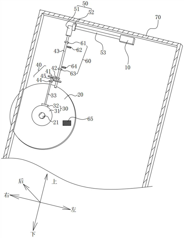
[0048] Such as figure 1As shown, the present invention provides a wheel rotating camera assembly, which is applied to mobile terminals, such as mobile phones, tablet computers and other devices. The wheel rotating camera assembly in the example includes a camera module 10, and the camera module 10 is used for imaging and shooting. The camera module 10 is usually set in the middle of the top, wherein the installation side of the camera module 10 is the upper side, and the side opposite to the upper side is the lower side, that is, the long side direction of the mobile phone is the up and down direction, and the mobile phone is used vertically. , the left and right sides are the left and right directions, and the directions corresponding to the mobile phone screen and the back panel are the front and rear directions. In this embodiment, the above-mentioned directions are used to set the benchmarks for describing the functional structures. The roller rotating camera assembly fu...

Embodiment 2

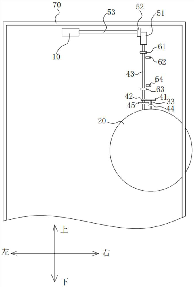
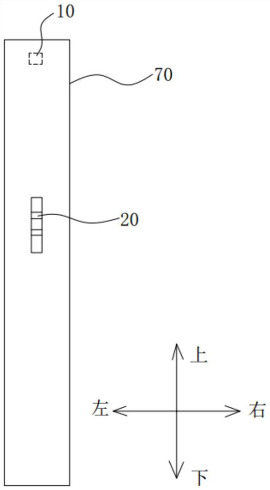
[0060] Such as image 3 As shown, based on the same idea, the present invention also proposes a mobile terminal, including a housing 70, and a display screen (not marked in the figure) covered on the housing, which also includes The above-mentioned roller rotating camera assembly, the camera module is rotatably set in the housing, the camera module 10 is set as an under-screen camera, the upper end surface and the upper end of the back of the housing are set as transparent areas, and the transparent areas match The rotation track of the camera module 10 .

[0061] The display screen is a display screen capable of realizing the under-screen display technology. There are many under-screen display technologies in mobile phones now, and the specific structure will not be introduced in detail in this embodiment. And through the display technology under the screen, according to the specific structural description of the first embodiment, the camera module 10 can realize the functio...

Embodiment 3

[0063] Based on the same idea, the present invention also proposes a method for controlling the wheel rotating camera assembly, wherein, it is used for the wheel rotating camera assembly as described in Embodiment 1 above, which includes steps:

[0064] Step S100, detecting and obtaining the toggling speed of the roller 20;

[0065] In this embodiment, the speed detector 65 is provided, and the speed of the roller 20 is sensed by the speed detector 65 . The speed is transmitted to the processor, and the corresponding control is realized after analysis by the processor. This realizes automatic control.

[0066] Step S200 , comparing the toggle rotation speed with a preset rotation speed, and changing the output rotation speed of the transmission assembly 40 according to the comparison result.

[0067] In this embodiment, the speed of the roller 20 detected by the speed detector 65 is received by the processor, compared with the preset preset value, and corresponding control i...


PUM


Abstract

The invention discloses a roller rotation camera assembly, a mobile terminal and a control method, and the assembly comprises a roller which is rotatably arranged; a first transmission assembly which is connected with the roller and converts shifting of the roller into rotation in the vertical direction; a variable speed transmission assembly which is connected with the first transmission assembly and used for changing the rotating speed of the first transmission assembly; a second transmission assembly which is connected to the variable speed transmission assembly and converts the rotation direction of the variable speed transmission assembly into rotation in the left-right direction; and a camera module which is connected to the second transmission assembly and is driven by the second transmission assembly to rotate in the left-right direction. The problem that the shooting angle is difficult to grasp due to the fact that the camera angle cannot be adjusted in the prior art is solved.

Description

technical field [0001] The invention relates to the technical field of cameras, in particular to a wheel rotating camera assembly, a mobile terminal and a control method. Background technique [0002] Nowadays, the cameras on smart terminal mobile phones generally have front-facing or rear-facing cameras. When taking a photo of a specific object or person, the subject needs to be shot vertically at 90°. That is to say, if you are shooting a standing object, you need to stand the phone upright so that you can get a good shot of the object. The angle of the shooting angle is fixed and cannot be adjusted, and the adjustment of the angle needs to be adjusted according to the placement. It depends on the angle of the phone. During the actual operation, it is difficult for personnel to control the 90° angle, so it is impossible to take natural photos. [0003] Therefore, the prior art still needs to be improved and developed. Contents of the invention [0004] In view of the...

Claims


Application Information

Patent Timeline
Patent Type & Authority Applications(China)
IPC IPC(8): H04M1/02H04N5/225
CPCH04M1/0264H04N23/57
Inventor 叶本志
Owner HUIZHOU TCL MOBILE COMM CO LTD
Why Eureka
Try Eureka