Mold stripping structure with buckles at two different angles

An angle and buckle technology, which is applied in the field of mold release structure, can solve the problems of increasing equipment loss, reducing production efficiency, and affecting the effect of mold release, so as to avoid equipment loss and ensure production efficiency.

Pending Publication Date: 2021-12-21
ZHEJIANG LEAPMOTOR TECH CO LTD
View PDF9 Cites 0 Cited by
  • Summary
  • Abstract
  • Description
  • Claims
  • Application Information

AI Technical Summary

Problems solved by technology

Generally, when designing the mold release structure, the buckle is ejected by using the inclined top. The inclined top and the buckle are integrally connected. The mold needs to move in two directions. If two inclined roofs are designed to be ejected at the same time, it will inevitably lead to motion interference (such as figure 2 As shown), it affects the effect of mold release. If the ejection of the two slanted ejectors is completely divided into two movements, the ejector rod of the injection molding machine is required to eject the two slanted ejectors twice, which will reduce production efficiency and increase equipment loss.

Method used


Image

  • Mold stripping structure with buckles at two different angles
  • Mold stripping structure with buckles at two different angles
  • Mold stripping structure with buckles at two different angles

Examples


specific Embodiment 1

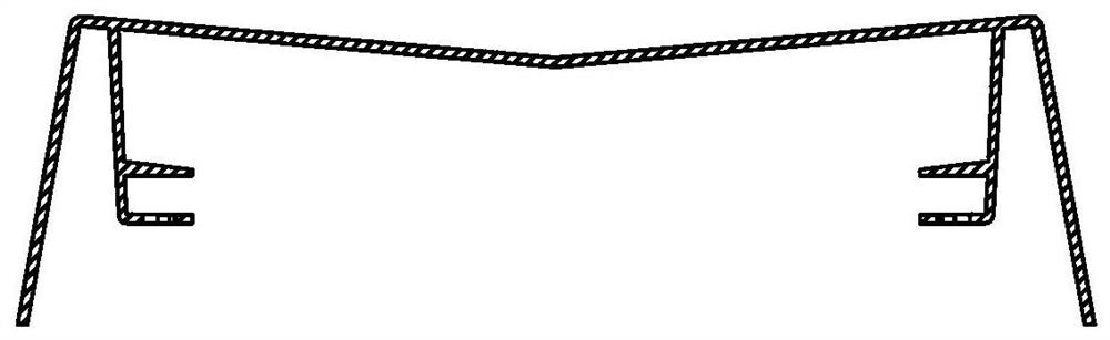
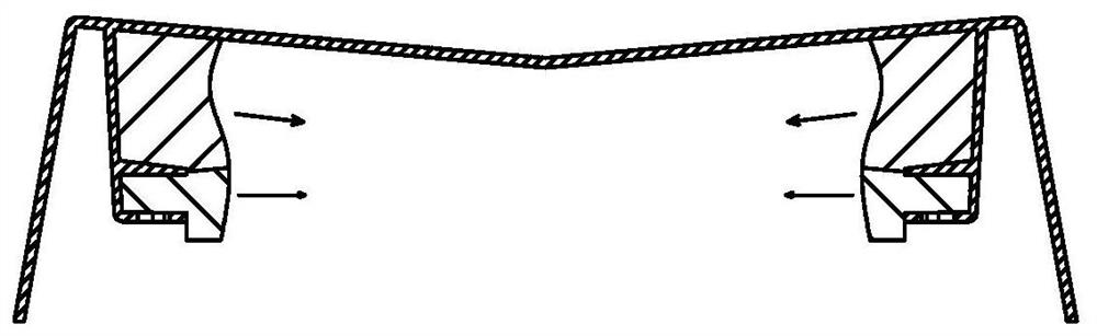
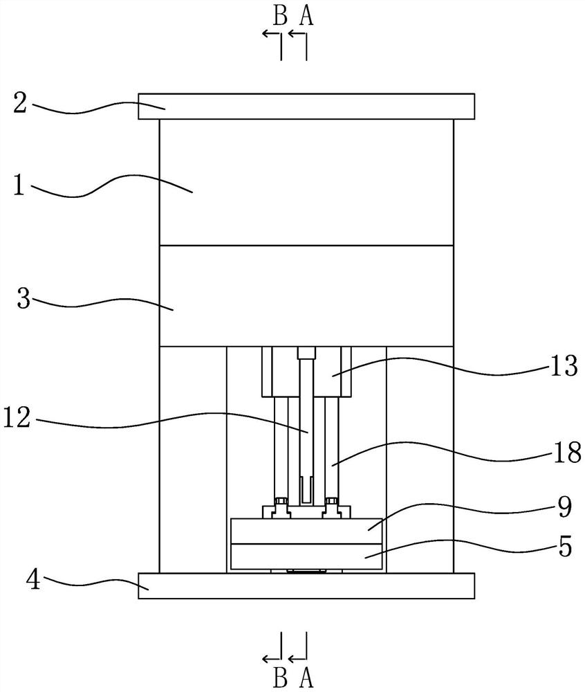
[0058] Specific embodiment one: as Figure 3 to Figure 7 As shown, a buckle has two different angles of ejection structure, including:

[0059] Upper mold 1, upper mold fixing plate 2, lower mold 3 and lower mold fixing plate 4;

[0060] Also includes:

[0061] The first ejector plate 5, the first ejector plate 5 is located above the lower mold fixing plate 4, the first ejector plate 5 is slid to be provided with a first slider 6; the first ejector plate 5 is provided with a jack block 7; the first ejector plate There is an ejector hole 8 on the top 5, and the ejector hole 8 runs through the first ejector plate 5 and the lower die fixing plate 4;

[0062] The second ejector plate 9, the second ejector plate 9 is located above the first ejector plate 5, and the second ejector plate 9 is provided with a second slide block 10; When the pull hook 11 hooks the top block 7;

[0063] The ejector pin 12, the ejector pin 12 is arranged at the lower part of the lower mold 3, and the...


PUM


Abstract

The invention discloses a mold stripping structure with buckles at two different angles. The mold stripping structure comprises an upper mold, an upper mold fixing plate, a lower mold, a lower mold fixing plate, a first ejector plate, a second ejector plate, an ejector rod and a moving block; a first sliding block is arranged on the first ejector plate in a sliding mode, and an ejector block is arranged in the first ejector plate; a second sliding block is slidably arranged on the second ejector plate, a drag hook is arranged at the lower part of the second ejector plate, and the drag hook hooks the ejector block when the ejector block is ejected out; a limiting groove is formed in the lower portion of the lower mold, the moving block is slidably arranged in the limiting groove, and the ejector block retracts when the moving block reaches the top of the limiting groove; the lower end of a first inclined rod is fixed to the first sliding block, and a first inclined top is fixed to the upper end of the first inclined rod; and the lower end of a second inclined rod is fixed to the second sliding block, and a second inclined top is fixed to the upper end of the second inclined rod. According to the mold stripping structure, two inclined tops are effectively combined through a mechanical structure, so that the two inclined tops do not interfere with each other; and in the whole mold stripping process, the ejector rod of an injection molding machine only needs to be ejected once, so that the production efficiency is ensured, and unnecessary equipment loss is avoided.

Description

technical field [0001] The invention relates to a mold-drawing structure, in particular to a mold-drawing structure with two different angles for buckles. Background technique [0002] The present invention is specifically applied to a certain injection molding product, and its schematic diagram is as follows figure 1 shown. If there is an inclined surface on the top of the product, the buckles that form the surface here need to move obliquely downward to release the mold. At the same time, the lower structure of the product needs to match the sheet metal, so the buckles that form the surface here need to move horizontally to be released. In this way, the buckles of the two profiles need to move in two directions when they are ejected from the mold. Generally, when designing the mold release structure, the buckle is ejected by using the inclined top. The inclined top and the buckle are integrally connected. The mold needs to move in two directions. If two inclined roofs a...

Claims


Application Information

Patent Timeline
IPC IPC(8): B29C45/40B29C45/44
CPCB29C45/4005B29C45/44B29C2045/445
Inventor 张伟伟龙刚启
Owner ZHEJIANG LEAPMOTOR TECH CO LTD
Why Eureka
Try Eureka