Laser marking tool

A technology of laser marking and tooling, which is applied in the field of laser marking, can solve the problems of consuming human resources, not having enough space for special-shaped elbows, and not being able to configure a large flat working platform for laser marking machines, so as to prevent front and rear offset effect

Pending Publication Date: 2021-12-24
镇江西门子母线有限公司
View PDF0 Cites 0 Cited by
  • Summary
  • Abstract
  • Description
  • Claims
  • Application Information

AI Technical Summary

Problems solved by technology

[0002] In each assembly group, due to space constraints, it is impossible to configure a large flat working platform for each laser marking machine
Therefore, when laser marking is performed, various problems will be encountered: different types and sizes of bus bar H profiles cannot be accurately positioned, resulting in label positions that cannot meet the requirements of process documents; various special-shaped elbows are not enough on site The marking operation cannot be realized due to the limited space; workers need to hold the marking parts with their hands, which consumes human resources

Method used


Image

  • Laser marking tool
  • Laser marking tool
  • Laser marking tool

Examples


Embodiment Construction

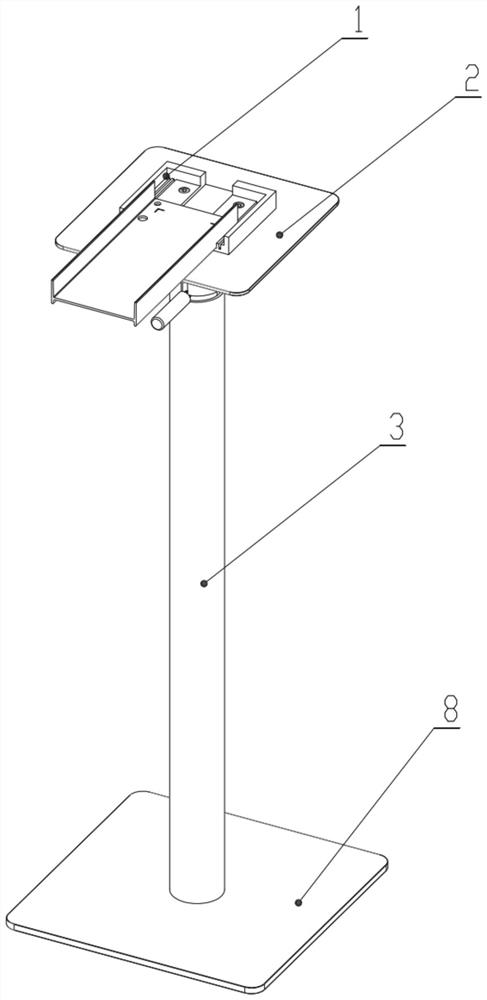
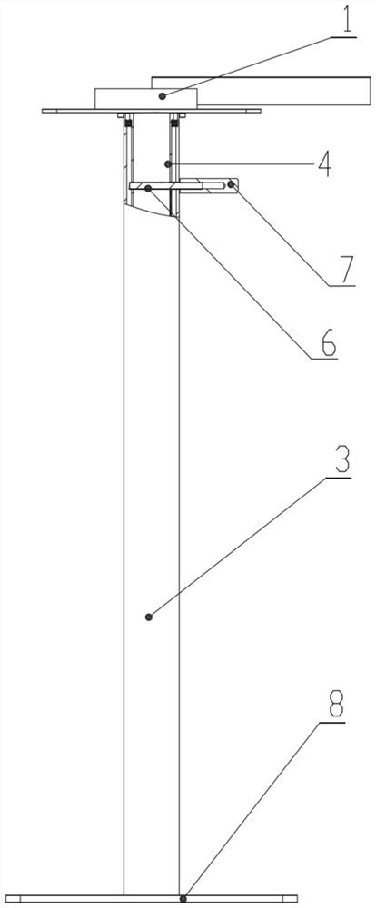
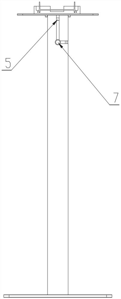
[0023] combine Figure 1-Figure 8 , this embodiment discloses a laser marking tool, including a limit working platform 1, the limit working platform 1 is used for placing H-shaped materials.

[0024] The overall outline of the position-limiting working platform 1 is a cuboid, including a bottom plate 11, a side wall 12, and a rear wall 13. The side walls 12 are respectively located on the left and right sides of the bottom plate 11, and the rear wall 13 is located on the rear side of the bottom plate 11. On the edge of the bottom plate 11, the front end of the space-limiting working platform 1 is an open structure, which is convenient for profiles to be sent to the bottom plate 11 from the front end, and the rear wall 13 also plays a position-limiting role to prevent the profiles from shifting back and forth.

[0025] There are also several card slots 14 on the bottom plate 11. The direction of the card slots 14 is from front to back, and the position of the card slots 14 is s...


PUM


Abstract

The invention relates to a laser marking tool which comprises a limiting working platform, a plurality of clamping grooves parallel in the front-back direction are formed in the limiting working platform, an opening is formed in the front end of the limiting working platform, and a protruding rear wall is arranged at the rear end of the limiting working platform. The front end of the limiting working platform is of an open structure so that a profile can be conveniently conveyed to a bottom plate from the front end, and the rear wall also plays a limiting effect to prevent the profile from deviating front and back. The multiple clamping grooves can be suitable for marking pieces of different specifications, and the marking pieces do not need to be manually supported in the marking process.

Description

technical field [0001] The invention relates to the field of laser marking, in particular to a laser marking tool. Background technique [0002] In each assembly group, due to space constraints, it is impossible to configure a large flat working platform for each laser marking machine. Therefore, when laser marking is performed, various problems will be encountered: different types and sizes of bus bar H profiles cannot be accurately positioned, resulting in label positions that cannot meet the requirements of process documents; various special-shaped elbows are not enough on site It is impossible to realize the marking operation if it is placed in a small space; workers need to hold the marking parts with their hands, which consumes human resources. Contents of the invention [0003] In order to solve the existing technical problems, the invention provides a laser marking tool. [0004] The specific content of the present invention is as follows: a laser marking tool, i...

Claims


Application Information

Patent Timeline
Patent Type & Authority Applications(China)
IPC IPC(8): B23K26/362B23K26/70
CPCB23K26/362B23K26/702
Inventor 戴健何小松赵惠敏唐孝健徐君龙
Owner 镇江西门子母线有限公司
Why Eureka
Try Eureka