
Autoclaved aerated concrete wallboard

A technology of autoclaved aeration and concrete, which is applied in the direction of walls, buildings, building components, etc., can solve the problems of complex wall panel steps, large manpower investment, and reduced construction progress, so as to achieve a good noise reduction environment, improve safety, and guarantee Efficiency effect

Pending Publication Date: 2021-12-24
HUZHOU HUINENG NEW MATERIAL TECH CO LTD
View PDF9 Cites 0 Cited by
  • Summary
  • Abstract
  • Description
  • Claims
  • Application Information

AI Technical Summary

Problems solved by technology

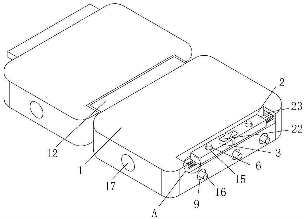
[0003] The purpose of the present invention is to solve at least one of the technical problems in the prior art, and to provide an autoclaved aerated concrete wall panel, which can solve the problem of complicated steps in the splicing and fixing of the wall panels, and a large amount of manpower input, which in turn leads to construction problems. Problems with slowing progress

Method used


Image

  • Autoclaved aerated concrete wallboard
  • Autoclaved aerated concrete wallboard
  • Autoclaved aerated concrete wallboard

Examples


Embodiment 1

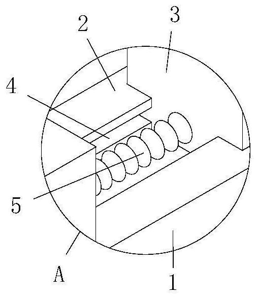
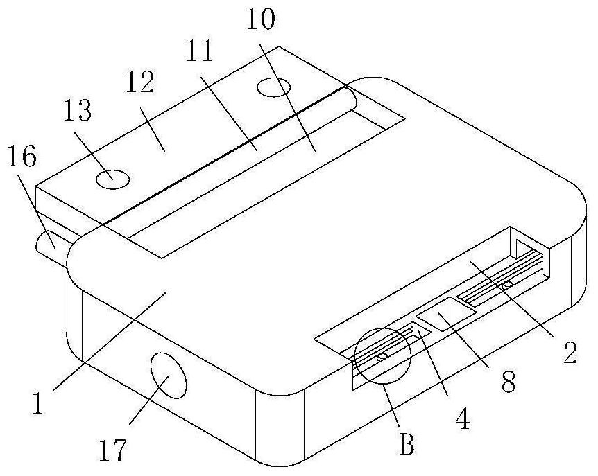
[0035] see Figure 1-5, the present invention provides a technical solution: an autoclaved aerated concrete wallboard, including two wallboards 1, the structures on the two wallboards 1 are the same, so the following mainly describes the structure on one wallboard 1, the wallboard The upper side of 1 is provided with a chute 2, and the inside of the chute 2 is slidably connected with a clamping plate 3, and the inside of the wall plate 1 is provided with a limiting groove 4 communicating with the chute 2, and the lower side of the clamping plate 3 is connected with the limiting groove 4. The shape of the groove 4 is cross-shaped, the lower side of the clamping plate 3 is slidably connected to the inside of the limiting groove 4, and the inside of the wallboard 1 is provided with a clamping groove 23 communicating with the chute 2 and the limiting groove 4. The left side of 3 is fixedly connected with return spring 5, and the left end of return spring 5 is fixedly connected in ...

Embodiment 2

[0038] see Image 6 , on the basis of Embodiment 1, the noise reduction buffer device includes an inner plate 18, the surface of the inner plate 18 is fixedly connected to the inside of the wall panel 1, and the surface of the inner plate 18 is provided with a flow groove 19, and the inside of the flow groove 19 is fixedly connected There is a fixed rod 21, and the surface of the fixed rod 21 is connected with the rotating plate 20, and the surface of the rotating plate 20 is connected with the rotation of the circulation groove 19. By putting the pouring pipe into the inside of the feed port 17, when the concrete enters the wallboard 1 After the interior, the concrete is in contact with the rotating plate 20, and through the rotation of the rotating plate 20 and the fixed rod 21, no direct impact will be generated between the concrete and the wall panel 1, and the rotation of the fixed rod 21 and the rotating plate 20 can play The protective effect on the wall panel 1 improve...


PUM


Abstract

The invention discloses an autoclaved aerated concrete wallboard, and relates to the field of buildings. The autoclaved aerated concrete wallboard comprises two wallboards, the structures of the two wallboards are the same, sliding grooves are formed in the upper sides of the wallboards, clamping plates are slidably connected into the sliding grooves, limiting grooves communicated with the sliding grooves are formed in the wallboards, and reset springs are fixedly connected to the left sides of the clamping plates. According to the autoclaved aerated concrete wallboard, when a rectangular plate is in butt joint with a fixing groove, the clamping plate slides from the interior of the sliding groove to the interior of a clamping groove till the butt joint of the rectangular plate and the fixing groove is completed and the clamping plate enters the clamping groove, so that the high efficiency of fixed splicing of the wallboard is guaranteed, the simplicity and convenience of limiting and fixing of the wallboard are improved, labor waste is greatly reduced during manual butt joint fixing, it is guaranteed that the clamping plate can be moved to reset quickly when the wallboard is not used through the elastic force of the reset spring, and the use simplicity of the clamping plate is guaranteed.

Description

technical field [0001] The invention relates to the technical field of construction, in particular to an autoclaved aerated concrete wall panel. Background technique [0002] For the development of the construction industry, the types of concrete wall panels are also endless, because the existing part of the wall panels requires multiple manpower to work at the same time to support and splice, and the wall panels need to be manually adjusted when splicing The position of the butt joint of the wall panels is used to achieve accuracy. This method leads to complicated steps in the splicing and fixing of the wall panels, and more manpower is invested, which in turn leads to problems such as a reduction in the construction progress. Contents of the invention [0003] The purpose of the present invention is to solve at least one of the technical problems in the prior art, and to provide an autoclaved aerated concrete wall panel, which can solve the problem of complicated steps...

Claims


Application Information

Patent Timeline
Patent Type & Authority Applications(China)
IPC IPC(8): E04B2/00E04C2/30E04B1/61
CPCE04B2/00E04C2/30E04B1/61
Inventor 曹铭敏段文虎
Owner HUZHOU HUINENG NEW MATERIAL TECH CO LTD
Learn More