Intelligent scenic spot tourist positioning device
A technology for positioning devices and scenic spots, which is applied to lighting devices, components of lighting devices, cooling/heating devices of lighting devices, etc. The effect of identifying the range, improving safety, facilitating rescue and taking out
- Summary
- Abstract
- Description
- Claims
- Application Information
AI Technical Summary
Problems solved by technology
Method used
Image
Examples
Embodiment 1
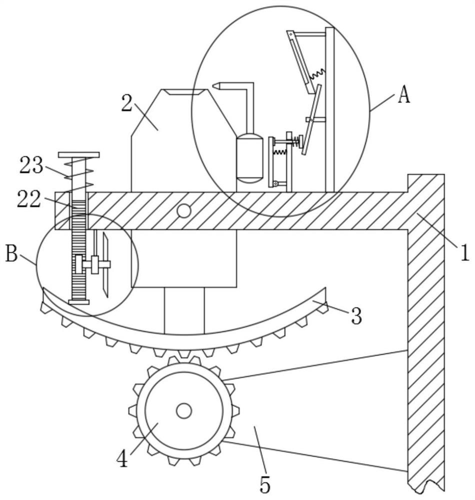
[0022] refer to Figure 1-3 , a positioning device for tourists in a smart scenic spot, comprising a bracket 1, a positioning light 2 is hinged on the support 1, an arc-shaped rack 3 is fixedly installed at the lower end of the positioning light 2, and a gear-4 is engaged with the middle part of the lower end of the arc-shaped rack 3, The gear one 4 rear end is fixedly installed with motor 5, and motor 5 right-hand ends are fixedly installed on the support 1, during use, this device is arranged in the multiple areas in the scenic spot, when the visitor gets lost in the scenic spot or needs rescue because of accident, can Find this device nearby, press the start button, drive the motor 5 to work, the motor 5 drives the gear one 4 to rotate forward and backward, the gear one 4 drives the arc rack 3 to rotate forward and reverse, and the arc rack 3 drives the positioning lamp 2 The support 1 rotates reciprocally forward and backward, and the positioning lamp 2 emits light to the ...
Embodiment 2
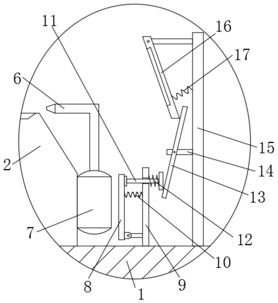
[0024] refer to Figure 1-3 , in this embodiment, it is basically the same as Embodiment 1, and more optimally, several nozzles 6 are provided on the upper right side of the positioning lamp 2, and the lower end of the nozzle 6 is connected with an airbag 7, and the airbag 7 is fixedly installed on the right end of the positioning lamp 2 , the right side of the airbag 7 is provided with a pressing plate 8, the lower side of the right end of the pressing plate 8 is hinged with a vertical plate 9, the lower end of the vertical plate 9 is fixedly installed on the support 1, the upper side of the right end of the pressing plate 8 is fixedly installed with a spring one 10, and the right end of the spring one 10 Fixedly installed on the vertical plate 9, when in use, when the positioning lamp 2 rotates, it will drive the air bag 7 and the nozzle 6 to approach the direction of the pressure plate 8, and then make the air bag 7 cooperate with the pressure plate 8, compress the air bag 7...
Embodiment 3
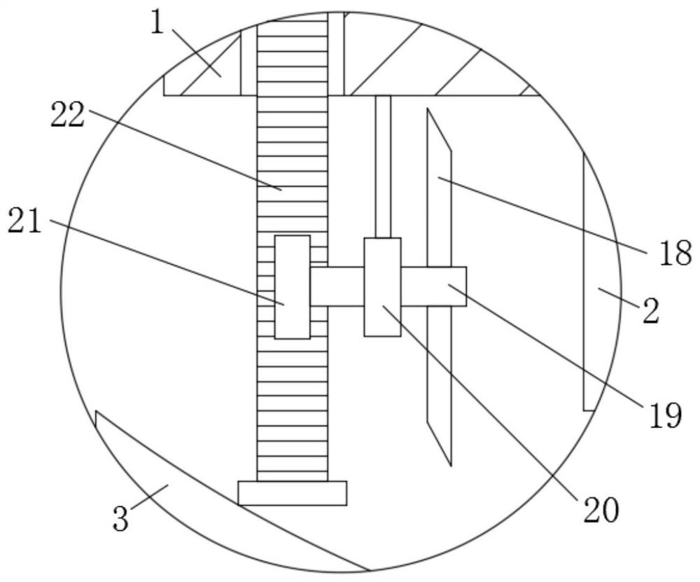
[0026] refer to Figure 1-3 , in this embodiment, it is basically the same as Embodiment 1, and more optimally, a lance 11 is provided on the right side of the pressure plate 8, and the left end of the lance 11 is attached to the pressure plate 8, and the lance 11 penetrates the vertical plate 9, and the The right side of the lance 11 is provided with a rotating plate 13, and the right end of the lance 11 is attached to the rotating plate 13. The spring 12 is sleeved on the lance 11, and the left and right ends of the spring 12 are fixedly installed on the vertical plate 9 and the ram respectively. On the bar 11, the right side of the lance 11 is provided with a rotating plate 13, the right end of the lance 11 is attached to the lower side of the left end of the rotating plate 13, the middle part of the rotating plate 13 is hinged with a fixed plate 14, and the right end of the fixed plate 14 is fixedly installed with a support plate 15, the lower end of the support plate 15 i...
PUM
 Abstract
Description
Claims
Application Information
 - R&D
- Intellectual Property
- Life Sciences
- Materials
- Tech Scout
- Unparalleled Data Quality
- Higher Quality Content
- 60% Fewer Hallucinations
Browse by: Latest US Patents, China's latest patents, Technical Efficacy Thesaurus, Application Domain, Technology Topic, Popular Technical Reports.
© 2025 PatSnap. All rights reserved.Legal|Privacy policy|Modern Slavery Act Transparency Statement|Sitemap|About US| Contact US: help@patsnap.com


