Method and device for presenting hierarchical relationship of view components

A hierarchical relationship and view technology, applied in the computer field

Pending Publication Date: 2021-12-24
BEIJING BYTEDANCE NETWORK TECH CO LTD
0 Cites 0 Cited by

AI-Extracted Technical Summary

Problems solved by technology

However, the functions provided by these product development tools or frameworks generally on...

Abstract

The embodiment of the invention discloses a method and device for presenting hierarchical relationships of view components. According to one specific embodiment, the method comprises: in response to detected operation used for indicating the viewing of the hierarchical relation of view components in a page, determining the offset of each hierarchy, wherein the offsets of different hierarchies are different; and for the hierarchy in each hierarchy, according to the offset corresponding to the hierarchy, shifting the area for displaying the view component in the hierarchy, and drawing the view component in the hierarchy in the shifted area. According to the embodiment, the view structure and the hierarchical relationship of the page can be viewed in real time.

Application Domain

Software engineeringExecution for user interfaces

Technology Topic

AlgorithmTheoretical computer science +2

Image

  • Method and device for presenting hierarchical relationship of view components
  • Method and device for presenting hierarchical relationship of view components
  • Method and device for presenting hierarchical relationship of view components

Examples

  • Experimental program(1)

Example Embodiment

[0030] The present disclosure will be further described in detail below with reference to the accompanying drawings and embodiments. It should be understood that the specific embodiments described herein are only used to explain the related invention, but not to limit the invention. In addition, it should be noted that, for the convenience of description, only the parts related to the related invention are shown in the drawings.
[0031] It should be noted that the embodiments of the present disclosure and the features of the embodiments may be combined with each other under the condition of no conflict. The present disclosure will be described in detail below with reference to the accompanying drawings and in conjunction with embodiments.
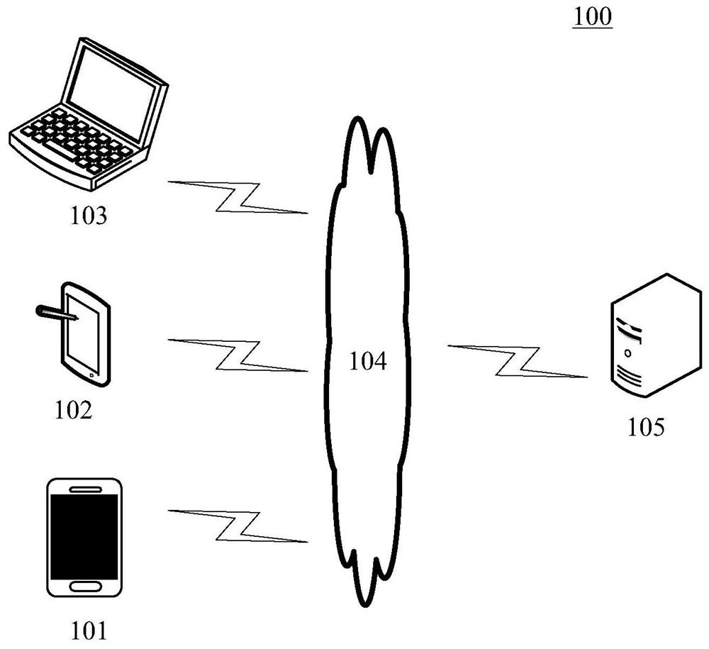
[0032] figure 1 An exemplary architecture 100 is shown to which embodiments of a method for presenting a hierarchical relationship of view components or an apparatus for presenting a hierarchical relationship of view components of the present disclosure may be applied.
[0033] like figure 1 As shown, the system architecture 100 may include terminal devices 101 , 102 , 103 , a network 104 and a server 105 . The network 104 is a medium used to provide a communication link between the terminal devices 101 , 102 , 103 and the server 105 . The network 104 may include various connection types, such as wired, wireless communication links, or fiber optic cables, among others.
[0034] The terminal devices 101, 102, and 103 interact with the server 105 through the network 104 to receive or send messages and the like. Various client applications may be installed on the terminal devices 101 , 102 and 103 . For example, browser applications, shopping applications, instant messaging applications, social platform software, information flow applications, etc.
[0035] The terminal devices 101, 102, and 103 may be hardware or software. When the terminal devices 101, 102, and 103 are hardware, they can be various electronic devices, including but not limited to smart phones, tablet computers, e-book readers, laptop computers, desktop computers, and the like. When the terminal devices 101, 102, and 103 are software, they can be installed in the electronic devices listed above. It can be implemented as multiple software or software modules (eg, multiple software or software modules for providing distributed services), or as a single software or software module. There is no specific limitation here.
[0036] The server 105 may be a server that provides various services, such as a backend server that provides support for client applications installed on the terminal devices 101 , 102 , and 103 . The server 105 may respond to the client request sent by the terminal devices 101 , 102 and 103 , and generate a response result to feed back to the terminal devices 101 , 102 and 103 .
[0037] It should be noted that the method for presenting the hierarchical relationship of the view components provided by the embodiments of the present disclosure is generally performed by the terminal devices 101, 102 and 103, and correspondingly, the apparatus for presenting the hierarchical relationship of the view components is generally set in in terminal devices 101, 102, and 103. At this point, server 105 and network 104 may be absent from example system architecture 100 .
[0038] It should also be pointed out that the server 105 may also have various types of applications installed, and the server 105 may also process the pages of the applications installed on the server 105 to present the hierarchical relationship of each view component in the page to the user. At this time, the method for presenting the hierarchical relationship of the view components may also be executed by the server 105 , and correspondingly, the apparatus for presenting the hierarchical relationship of the view components may also be provided in the server 105 . At this point, the example system architecture 100 may not have the terminal devices 101 , 102 , 103 and the network 104 present.
[0039] It should be noted that the server 105 may be hardware or software. When the server 105 is hardware, it can be implemented as a distributed server cluster composed of multiple servers, or can be implemented as a single server. When the server 105 is software, it can be implemented as multiple software or software modules (for example, multiple software or software modules for providing distributed services), or can be implemented as a single software or software module. There is no specific limitation here.
[0040] It should be understood that figure 1 The numbers of terminal devices, networks and servers in are only illustrative. There can be any number of terminal devices, networks and servers according to implementation needs.
[0041] continue to refer to figure 2 , which shows a flow 200 of one embodiment of a method for presenting a hierarchical relationship of view components according to the present disclosure. The method for presenting the hierarchical relationship of view components includes the following steps:
[0042] Step 201, in response to detecting the operation for indicating the hierarchical relationship of the view components in the viewing page, determine the offset of each level.
[0043] In this embodiment, the execution body for presenting the hierarchical relationship of the view components (such as figure 1 The illustrated terminal devices 101, 102, 103, etc.) can determine the offset of each view level in the current page when detecting an operation for instructing to view the hierarchical relationship of the view components in the current page.
[0044] The page may refer to the page displayed by the display device of the above-mentioned execution body. For example, the page may be the current running page of the client application installed on the execution body. For another example, the page may be a page of a terminal application that the tester is testing.
[0045] View components (or controls) may refer to various UI (User Interface, user interface) elements in a page. Every UI element can be thought of as a view component. As examples, view components include, but are not limited to: text boxes, buttons, date/time controls, tree controls, list boxes, and the like.
[0046] Generally, the layout of a page is pre-set by developers according to a certain hierarchical relationship. That is, there is a hierarchical relationship between the view components in the page. The layout of a page can usually be represented as a tree structure. At this point, each node in the tree structure represents a view component in the page. Each level in the tree structure can represent a view level that the page has.
[0047] In this embodiment, the operation for indicating the hierarchical relationship of the view components in the viewing page may be various user operations. For example, the operation for indicating the hierarchical relationship of view components in the viewing page may be a pre-specified operation (eg, double-clicking a specified area of ​​the page or pressing an execution button on a terminal, etc.). For another example, the operation for indicating the hierarchical relationship of view components in the viewing page may be a pre-designed voice instruction or the like.
[0048] The above-mentioned execution body may flexibly adopt various offsets corresponding to each level in the current page layout according to actual application requirements and different application scenarios. Generally, the offsets of different levels can be different to express the hierarchical relationship.
[0049] For example, offsets corresponding to each level in the page layout may be preset. As an example, the offsets of each layer are set in advance in order from the top layer to the bottom layer. In this case, the preset offset corresponding to each level in the current page layout may be acquired after receiving the operation for indicating the hierarchical relationship of the view components in the viewing page.
[0050] The offset may refer to the degree of offset from the current position to the specified direction. According to different application requirements, the specific representation method of the offset can be different. For example, the offset amount may indicate an offset in a specified direction (eg, the horizontal direction).
[0051] Optionally, the offset may indicate that the offset is performed in both the horizontal and vertical directions. At this time, the offset amount may include an offset amount in a horizontal direction and an offset amount in a vertical direction.
[0052] Step 202 , for a level in each level, according to the offset corresponding to the level, offset the area where the view components in the level are displayed, and draw the view components in the level in the shifted area.
[0053] In this embodiment, the area in which the view components in the hierarchy are displayed may refer to a display area for displaying each view component in the hierarchy. In some cases, the display areas corresponding to each level may be the same.
[0054] By offsetting the display areas of different levels to different degrees, and drawing the view components in the corresponding levels in the offset display areas, the relationship between different levels can be displayed, so that users can understand each view. Structural relationships between components.
[0055] It should be understood that in different application scenarios, different methods for offsetting the area of ​​the view component in the display hierarchy and different methods for drawing the view component may be specifically adopted.
[0056] As an example, if the above-mentioned execution body adopts the Android operating system, the page is a running page of a client application installed on the above-mentioned execution body. At this time, the area for displaying the view components in the hierarchy may be a canvas (Canvas). Offset the area of ​​the view component in the display hierarchy is to offset the canvas object corresponding to the current page. Specifically, the offset can be performed by calling the corresponding offset methods (such as offsetX() and offsetY() methods, etc.) by using the Canvas object. After that, you can use the Canvas object to call the corresponding drawing method (such as the draw() method, etc.) to draw each view component in the hierarchy.
[0057] It should be noted that, when the display areas corresponding to each level are the same, each time the offset performed on the area of ​​the view component in the display level is the offset performed with respect to the current position of the area. In other words, after an area is offset once, the next offset of the area is not an offset to the location of the area after one offset, but an offset to the original location of the area .
[0058] Therefore, for a level in each level, the display area is offset according to the offset corresponding to the level, and after the view components in the level are drawn in the offset area, for the next level, you need to first The area is restored to its position before it was not offset, and then a new offset is performed on the display area according to the offset corresponding to this level, and the view components in this level are drawn in the newly offset area.
[0059] Optionally, when drawing the view components in each layer, the content originally displayed by the view components can be drawn at the same time, so that the user can view all the displayed content of the current page while understanding the hierarchical relationship of the view components.
[0060] In some optional implementations of this embodiment, the offsets of the levels in each level may be positively correlated with the depth of the levels. In other words, the level above other levels has the largest offset, and the level below other levels has the smallest offset.
[0061] For example, the offset corresponding to each level may be determined based on the product of the depth of the level and a preset offset.
[0062] As a result, the positional relationship between the levels can be further made clearer, and the comparison of the hierarchical relationship between the view components in the page can be made clearer, so that the relevant personnel can more easily see the level between the view components in the page. relation.
[0063] In some optional implementations of this embodiment, in response to detecting a target transformation operation for instructing the shifted region, transform processing is performed on the shifted region according to the target transformation operation.
[0064] The target transformation operation may include at least one of the following: an operation for instructing zooming in, an operation for instructing zooming out, and an operation for instructing rotation. The target changing operation can be various preset user operations.
[0065] At this time, after offsetting the area displaying the view components in each level according to the corresponding offset and redrawing the view components, according to the detected target transformation operation, the offsets and offsets of the view components in the display level can be further adjusted. The moved area can be enlarged, reduced, rotated, etc., so as to increase the flexibility of the user's control over the page effect.
[0066] Still taking the Android operating system as the above-mentioned execution body, and the page as an example of the running page of a client application installed on the above-mentioned execution body, at this time, the canvas can be enlarged according to the detected target transformation operation (such as the scale() method etc.), shrinking (such as scale() method, etc.), rotation (such as rotate() method, etc.), etc., so that users can flexibly control the display effect of the page according to their needs, and observe and understand each page from various angles. The hierarchy of view components.
[0067] In some optional implementations of this embodiment, a pre-developed hierarchical processing class for presenting a hierarchical relationship of views may be used to obtain the position information corresponding to each view component in the current page, and store the position information in a tree structure. obtained location information.
[0068] It should be understood that the above tree structure may correspond to the positional relationship between the view components. The location information of the view component may include relative location information for indicating the location of the view component in the region where the view component is located and hierarchical location information for indicating the level in which the view component is located. Among them, the relative position information and the hierarchical position information of the view components can be expressed in various ways flexibly.
[0069] For example, the relative position information of a view component can be represented by the position of the view component relative to the upper left corner of the region in which it is located. The hierarchical position information of a view component can be represented by the depth of the hierarchy in which the view component is located.
[0070] In this way, the structure and positional relationship between the view components in the page can be easily understood. At this time, for each level, after offsetting the level according to the offset corresponding to the level, the The view components in the hierarchy are drawn at the positions indicated by the position information corresponding to each view component in the hierarchy.
[0071] In some optional implementations of this embodiment, the position information corresponding to each view component in the page may be obtained by using the above-mentioned hierarchical processing class in the following manner: using the object created based on the hierarchical processing class as each view component in the page The root view of the page; according to the layout information of each view component in the page, the position information corresponding to each view component in the page is obtained.
[0072] Still taking the Android operating system as the above-mentioned execution body, and the page being a running page of a client application installed on the above-mentioned execution body as an example, the hierarchical processing class may be a container class. Specifically, when receiving a request for viewing the hierarchical relationship of view components in the current page, all view contents under the root view of the current window (window) can be removed, and the removed view contents can be added to Based on the container created by the hierarchical processing class, the created container is added as content to the root view of the current window. In this way, the position information corresponding to each view component in the page can be obtained by means of recursion or the like by using the hierarchical processing class.
[0073] It should be understood that at this time, the area offset method for view components in the display hierarchy and the drawing method for view components in the display hierarchy can be rewritten by using the hierarchy processing class to offset each hierarchy level and draw the view components in the hierarchy.
[0074]Optionally, when a request indicating to close the hierarchical relationship of the view components in the current page is received, the content added in the created container can be removed, and the removed content can be added to the current window (window). Under the root view, the original processing logic of the application is restored, and the hierarchical relationship of the view components in the current page is no longer presented to the user in response to the operation for indicating the hierarchical relationship of the view components in the viewing page.
[0075] In some optional implementation manners of this embodiment, the foregoing executive body may display a pre-developed switch control (eg, switch). At this time, the user can control whether to present the hierarchical relationship of the view components in the current page by turning the switch control on or off. When the switch control is on, the above steps 201 and 202 can be performed so that the user can view the hierarchical relationship of the view components in the current page through operations. When the switch control is off, the user can only browse the real-time running effect of the page, and can no longer view the hierarchical relationship of the view components in the current page through related operations. Thus, the user can control on or off the function of viewing the hierarchical relationship of the view components in the current page in real time according to the current demand.
[0076] For example, developers can pre-set debug backdoors and set the aforementioned switch controls. Therefore, the developer can conveniently control the switch control to be on to view the hierarchical relationship of the view components in the currently running page in real time, so as to provide help for the developer to analyze the problems related to the current page or optimize the current page. At the same time, the developer can also turn off the switch control to turn off the display of the hierarchical relationship of the view components in the page, so as to provide convenience for the developer's work.
[0077] The methods provided by the foregoing embodiments of the present disclosure detect an operation for indicating viewing the hierarchical relationship of view components in the current page, and when the operation is detected, determine the offsets corresponding to each view hierarchy of the current page, and According to the determined offset, the corresponding offset is performed on each level, and the view components in the level are drawn in the offset display area corresponding to the level, so that the positional relationship between different levels can be presented. In order to distinguish different levels, it is convenient for relevant personnel to view the hierarchical relationship between the view components in the current page in real time during the running process of the application.
[0078] further reference image 3 , which shows a flow 300 of yet another embodiment of a method for presenting a hierarchical relationship of view components. The process 300 of the method for presenting the hierarchical relationship of view components includes the following steps:
[0079] Step 301, in response to detecting a gesture operation for indicating the hierarchical relationship of view components in the viewing page, determine the offset of each level according to the detected gesture operation.
[0080] In this embodiment, the gesture operation may be various types of gesture operations, which may be preset by a technician according to actual application requirements or application scenarios. For example, gesture operations may include contact gesture operations, non-contact gesture operations, and the like.
[0081] The corresponding relationship between the gesture operation and the offset of each level can be pre-designed by the skilled person. At this time, the offset of each level can be calculated by using the pre-designed correspondence according to the detected gesture operation.
[0082] For example, the gesture operation may include a one-finger swipe operation. At this time, the corresponding relationship between the operation attributes (such as the sliding direction and the sliding distance, etc.) of the single-finger sliding operation and the offset of each level can be designed in advance.
[0083] Step 302 , for a level in each level, according to the offset corresponding to the level, offset the area where the view components in the level are displayed, and draw the view components in the level in the shifted area.
[0084] For the specific execution process of this step 302, please refer to figure 2 Corresponding descriptions of step 202 in the embodiment are not repeated here.
[0085] Optionally, after the region displaying the view components in each level is offset according to the corresponding offset and the view components are redrawn, according to the detected gesture operation for instructing the shifted region to be transformed, The offset area can be further enlarged, reduced, rotated, etc., so that the user can control the page presentation effect through convenient gesture operation. For example, different two-finger operations can be used to respectively indicate a zoom-in operation, a zoom-out operation, and a rotation operation on the area where the view components in each hierarchy are displayed.
[0086] It should be understood that, as the user's gestures change, the above-mentioned executive body can continuously perform the above steps 301 and 302 to continuously present the hierarchical relationship of each view component in the current page at different angles or degrees according to the user's gestures.
[0087] continue to see Figure 4 , Figure 4 It is a schematic application scenario 400 of the method for presenting the hierarchical relationship of view components according to this embodiment. As shown by the icon number 401 , the page displayed by the terminal includes control 1 , control 2 , control 3 and control 4 . When the user's sliding operation in the upper left direction is detected, the offset of each view level (including the offset in the horizontal direction and the offset in the vertical direction) is calculated according to the direction and distance of the detected sliding operation, and Offset the display area of ​​each level in turn according to the corresponding offset, and draw each component according to the position of each view component in the level relative to the display area, so as to obtain a presentation with various components as shown by the reference number 402 in the figure. The page effect of the hierarchical relationship between view components.
[0088] It can be clearly seen from the page indicated by the number 402 in the figure that among the four controls on the current page, control 1 is located at the top level, control 2 is located at the second level below the top level, control 3 is located at the third level, and control 4 is located in all The lowest level of the view hierarchy.
[0089] The method provided by the above-mentioned embodiments of the present disclosure supports the user to use gesture operations to control the presentation and transformation of the hierarchical relationship of components in real time, so that the user can more flexibly view the hierarchical relationship of the view components in the page according to their own needs, and can view the hierarchical relationship from different View the hierarchical relationship of the view components in the current page from an angle and an all-round perspective.
[0090] further reference Figure 5 , as an implementation of the methods shown in the above figures, the present disclosure provides an embodiment of an apparatus for presenting a hierarchical relationship of view components, the apparatus embodiment is the same as figure 2 Corresponding to the method embodiments shown, the apparatus can be specifically applied to various electronic devices.
[0091] like Figure 5 As shown, the apparatus 500 for presenting a hierarchical relationship of view components provided in this embodiment includes a determining unit 501 and a drawing unit 502 . Wherein, the determining unit 501 is configured to, in response to detecting the operation for indicating the hierarchical relationship of the view components in the viewing page, determine the offsets of each level, wherein the offsets of different levels are different; the drawing unit 502, It is configured to, for each level in the level, offset the area where the view components in the level are displayed according to the offset corresponding to the level, and draw the view components in the level in the shifted area.
[0092] In this embodiment, in the apparatus 500 for presenting the hierarchical relationship of view components: the specific processing of the determining unit 501 and the drawing unit 502 and the technical effects brought about by the determining unit 501 can be referred to respectively. figure 2 Corresponding descriptions of step 201 and step 202 in the embodiment will not be repeated here.
[0093] In some optional implementations of this embodiment, the above-mentioned operations include gesture operations; and the above-mentioned determination unit 501 is further configured to: determine the offset of each level according to the above-mentioned operations.
[0094] In some optional implementations of this embodiment, the offsets of the levels in each level are positively related to the depth of the levels.
[0095] In some optional implementations of this embodiment, the above-mentioned apparatus 500 for presenting a hierarchical relationship of view components further includes: a transforming unit (not shown in the figure) configured to respond to the detection of a pair of offsets The target transformation operation of the rear area is to perform transformation processing on the shifted region according to the target transformation operation, wherein the target transformation operation includes at least one of the following: an operation for indicating enlargement, an operation for indicating reduction, and an operation for indicating Rotation operation.
[0096] In some optional implementations of this embodiment, the above-mentioned apparatus 500 for presenting a hierarchical relationship of view components further includes: an acquiring unit (not shown in the figure) configured to use a pre-developed method for presenting a view The hierarchical processing class of the hierarchical relationship obtains the position information corresponding to each view component in the page, wherein the position information of the view component includes the relative position information used to indicate the position of the view component in the area where it is located and the position information used to indicate the view component Hierarchical location information of the level where it is located; the acquired location information is stored in a tree structure.
[0097] In some optional implementations of this embodiment, the above-mentioned obtaining unit is further configured to: use the object created based on the hierarchical processing class as the root view of each view component in the page; according to the layout information of each view component in the page , to obtain the location information corresponding to each view component in the page.
[0098] In some optional implementations of this embodiment, the above offset includes an offset in a horizontal direction and an offset in a vertical direction.
[0099] In the apparatus provided by the above-mentioned embodiments of the present disclosure, in response to detecting the operation for indicating the hierarchical relationship of view components in the viewing page, the determination unit determines the offset of each level, wherein the offset of different levels is different; Drawing unit For the levels in each level, according to the offset corresponding to the level, offset the area where the view components in the level are displayed, and draw the view components in the level in the offset area, so that you can The positional relationship between different levels is presented, so that the relevant personnel can directly and clearly understand the hierarchical relationship between the view components in the page.
[0100] Reference below Image 6 , which illustrates an electronic device suitable for use in implementing embodiments of the present disclosure (eg, figure 1 Schematic diagram of the structure of the terminal equipment) 600. Terminal devices in the embodiments of the present disclosure may include, but are not limited to, such as mobile phones, notebook computers, digital broadcast receivers, PDAs (Personal Digital Assistants), PADs (Tablets), PMPs (Portable Multimedia Players), vehicle-mounted terminals ( For example, mobile terminals such as car navigation terminals) and the like, and stationary terminals such as digital TVs, desktop computers, and the like. Image 6 The illustrated terminal device is only an example, and should not impose any limitation on the function and scope of use of the embodiments of the present disclosure.
[0101] like Image 6 As shown, electronic device 600 may include processing means (eg, central processing unit, graphics processor, etc.) 601 that may be loaded into random access memory (RAM) according to a program stored in read only memory (ROM) 602 or from storage means 608 ) 603 to execute various appropriate actions and processes. In the RAM 603, various programs and data necessary for the operation of the electronic device 600 are also stored. The processing device 601 , the ROM 602 , and the RAM 603 are connected to each other through a bus 604 . An input/output (I/O) interface 605 is also connected to bus 604 .
[0102]Typically, the following devices can be connected to the I/O interface 605: input devices 606 including, for example, a touch screen, touchpad, keyboard, mouse, camera, microphone, accelerometer, gyroscope, etc.; including, for example, a liquid crystal display (LCD), speakers, vibration An output device 607 of a computer, etc.; a storage device 608 including, for example, a magnetic tape, a hard disk, etc.; and a communication device 609. Communication means 609 may allow electronic device 600 to communicate wirelessly or by wire with other devices to exchange data. Although Image 6 Electronic device 600 is shown having various means, but it should be understood that not all of the shown means are required to be implemented or provided. More or fewer devices may alternatively be implemented or provided. Image 6 Each block shown in can represent one device, and can represent multiple devices as needed.
[0103] In particular, according to embodiments of the present disclosure, the processes described above with reference to the flowcharts may be implemented as computer software programs. For example, embodiments of the present disclosure include a computer program product comprising a computer program carried on a computer-readable medium, the computer program containing program code for performing the method illustrated in the flowchart. In such an embodiment, the computer program may be downloaded and installed from the network via the communication device 609 , or from the storage device 608 , or from the ROM 602 . When the computer program is executed by the processing apparatus 601, the above-described functions defined in the methods of the embodiments of the present disclosure are executed.
[0104] It should be noted that the computer-readable medium described in the embodiments of the present disclosure may be a computer-readable signal medium or a computer-readable storage medium, or any combination of the above two. The computer-readable storage medium can be, for example, but not limited to, an electrical, magnetic, optical, electromagnetic, infrared, or semiconductor system, apparatus or device, or a combination of any of the above. More specific examples of computer readable storage media may include, but are not limited to, electrical connections with one or more wires, portable computer disks, hard disks, random access memory (RAM), read only memory (ROM), erasable Programmable read only memory (EPROM or flash memory), fiber optics, portable compact disk read only memory (CD-ROM), optical storage devices, magnetic storage devices, or any suitable combination of the foregoing. In embodiments of the present disclosure, a computer-readable storage medium may be any tangible medium that contains or stores a program that can be used by or in conjunction with an instruction execution system, apparatus, or device. Rather, in embodiments of the present disclosure, a computer-readable signal medium may include a data signal in baseband or propagated as part of a carrier wave, carrying computer-readable program code therein. Such propagated data signals may take a variety of forms, including but not limited to electromagnetic signals, optical signals, or any suitable combination of the foregoing. A computer-readable signal medium can also be any computer-readable medium other than a computer-readable storage medium that can transmit, propagate, or transport the program for use by or in connection with the instruction execution system, apparatus, or device . Program code embodied on a computer readable medium may be transmitted using any suitable medium including, but not limited to, electrical wire, optical fiber cable, RF (radio frequency), etc., or any suitable combination of the foregoing.
[0105] The above-mentioned computer-readable medium may be included in the above-mentioned terminal; or may exist alone without being assembled into the terminal. The above-mentioned computer-readable medium carries one or more programs, and when the above-mentioned one or more programs are executed by the terminal, make the terminal: in response to detecting an operation for indicating the hierarchical relationship of the view components in the viewing page, determine The offsets of each level, wherein the offsets of different levels are different; for the levels in each level, according to the offset corresponding to the level, the area where the view components in the level are displayed is offset, and the offset is The view components in this hierarchy are drawn in the moved area.
[0106] Computer program code for carrying out operations of embodiments of the present disclosure may be written in one or more programming languages, including object-oriented programming languages—such as Java, Smalltalk, C++, or a combination thereof, Also included are conventional procedural programming languages ​​- such as the "C" language or similar programming languages. The program code may execute entirely on the user's computer, partly on the user's computer, as a stand-alone software package, partly on the user's computer and partly on a remote computer, or entirely on the remote computer or server. In the case of a remote computer, the remote computer may be connected to the user's computer through any kind of network, including a local area network (LAN) or a wide area network (WAN), or may be connected to an external computer (eg, using an Internet service provider to via Internet connection).
[0107] The flowchart and block diagrams in the Figures illustrate the architecture, functionality, and operation of possible implementations of systems, methods and computer program products according to various embodiments of the present disclosure. In this regard, each block in the flowchart or block diagrams may represent a module, segment, or portion of code that contains one or more logical functions for implementing the specified functions executable instructions. It should also be noted that, in some alternative implementations, the functions noted in the blocks may occur out of the order noted in the figures. For example, two blocks shown in succession may, in fact, be executed substantially concurrently, or the blocks may sometimes be executed in the reverse order, depending upon the functionality involved. It is also noted that each block of the block diagrams and/or flowchart illustrations, and combinations of blocks in the block diagrams and/or flowchart illustrations, can be implemented in dedicated hardware-based systems that perform the specified functions or operations , or can be implemented in a combination of dedicated hardware and computer instructions.
[0108] The units involved in the embodiments of the present disclosure may be implemented in software or hardware. The described unit can also be provided in the processor, for example, it can be described as: a processor includes a determination unit and a drawing unit. Wherein, the names of these units do not constitute a limitation of the unit itself in some cases, for example, the determination unit may also be described as "in response to detecting an operation for indicating the hierarchical relationship of view components in the viewing page, The unit that determines the offset of each level".
[0109] The above description is merely a preferred embodiment of the present disclosure and an illustration of the technical principles employed. Those skilled in the art should understand that the scope of the invention involved in the embodiments of the present disclosure is not limited to the technical solution formed by the specific combination of the above-mentioned technical features, and should also cover, without departing from the above-mentioned inventive concept, the above-mentioned Other technical solutions formed by any combination of technical features or their equivalent features. For example, a technical solution is formed by replacing the above-mentioned features with the technical features disclosed in the embodiments of the present disclosure (but not limited to) with similar functions.

PUM

no PUM

Description & Claims & Application Information

We can also present the details of the Description, Claims and Application information to help users get a comprehensive understanding of the technical details of the patent, such as background art, summary of invention, brief description of drawings, description of embodiments, and other original content. On the other hand, users can also determine the specific scope of protection of the technology through the list of claims; as well as understand the changes in the life cycle of the technology with the presentation of the patent timeline. Login to view more.
Why Eureka
Try Eureka