Novel cable bridge

A cable bridge, a new type of technology, applied in the direction of electrical components, etc., can solve the problems of limited angle adjustment range, inconvenient installation, waste of manpower and time, etc., to achieve stepless adjustment self-locking locking, simple and effective adjustment mechanism, accurate and stable adjustment Effect

Active Publication Date: 2021-12-24
国网山东省电力公司利津县供电公司 +1
View PDF6 Cites 4 Cited by
  • Summary
  • Abstract
  • Description
  • Claims
  • Application Information

AI Technical Summary

Problems solved by technology

[0002] Cable trays are used to install and fix cables, and are divided into trough type, tray type, ladder frame type, grid type and other structures. The bridge frame in the building can be erected independently, or It can be attached to various buildings and pipe gallery supports. The cable bridge is a linear structure. When corners are required, two bridges need to be welded and connected, which is very inconvenient to install.
[0003] When the corner angle needs to be adjusted, the cable can only be taken out, the bridge frame is cut off and welded again, which is very inconvenient and wastes manpower and time during construction
[0004] In the prior art, there are also cable trays that can adjust the angle, but most of them have a limited range of angle adjustment and the adjustment method is not simple enough, which affects the use and installation on site

Method used


Image

  • Novel cable bridge
  • Novel cable bridge
  • Novel cable bridge

Examples


Embodiment Construction

[0041] The present invention will be described in further detail below in conjunction with the accompanying drawings.

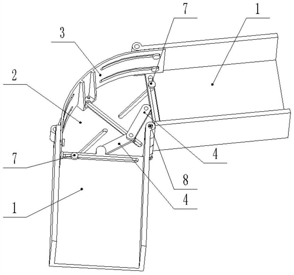
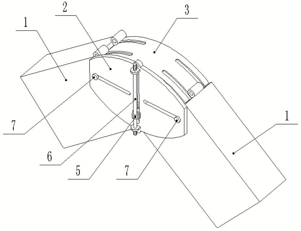
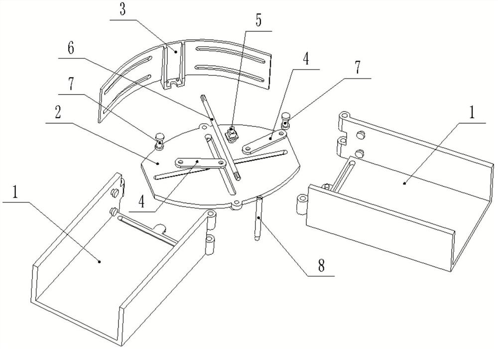
[0042] A new type of cable tray, comprising: two mutually hinged straight slots 1, the straight slots 1 are generally formed by bending plates, the two straight slots 1 are connected by rotation and the included angle is adjustable. The bottoms of the two straight grooves 1 are connected and fixed by connecting the bottom plate 2 . There is a flexible connection between the connecting bottom plate 2 and the straight groove 1. The cables are laid in the channel formed by the two straight grooves 1 and the connection base plate 2 .

[0043] In order to realize the adjustable angle between the two straight grooves 1, the device is also equipped with an adjustment mechanism.

[0044] An embodiment of the adjustment mechanism includes: a slide block 5 slidably arranged on the connection base plate 2, a boss 102 is provided on the straight groove 1, a connecting ...


PUM


Abstract

The invention relates to a novel cable bridge which comprises straight grooves hinged to each other. The bottoms of the two straight grooves are connected and fixed through a connecting bottom plate, and the included angle between the two straight grooves is adjustable. A sliding block is arranged on the connecting bottom plate in a sliding manner, a boss is arranged on the straight groove, and a connecting rod is arranged between the sliding block and the boss. A vertically-through center guide groove is formed in the connecting bottom plate, a lead screw is rotatably arranged at the lower end of the connecting bottom plate, and the sliding block is slidably arranged in the center guide groove; the upper end of the sliding block is rotatably connected with the connecting rod, the lower end of the sliding block is in threaded connection with the lead screw, and an outer vertical plate is arranged between the side vertical surfaces of the two straight grooves. A vertically-through first sliding groove is formed in the straight groove, a vertically-through second sliding groove is formed in the connecting bottom plate, and a shaft pin is inserted in the crossed and overlapped position of the first sliding groove and the second sliding groove. The invention further discloses a cable corner adjusting method which can adjust the corner of the cable bridge and can meet the installation requirements under various use working conditions.

Description

technical field [0001] The invention relates to the technical field of circuit equipment, in particular to a novel cable tray. Background technique [0002] The cable bridge is used to install and fix cables, and it is divided into trough type, tray type, ladder frame type, grid type and other structures. The bridge frame in the building can be erected independently or attached to various buildings and pipe gallery supports. Cable bridge It is a straight-line structure. When a corner is required, two bridges need to be welded and connected, which is very inconvenient to install. [0003] When the corner angle needs to be adjusted, the cable can only be taken out, the bridge frame is cut off and welded again, which is very inconvenient and wastes manpower and time during construction. [0004] There are also cable trays that can adjust the angle in the prior art, but most of them have a limited range of angle adjustment and the adjustment method is not simple enough, which a...

Claims


Application Information

Patent Timeline
Patent Type & Authority Applications(China)
IPC IPC(8): H02G3/06H02G3/04H02G3/34
CPCH02G3/0608H02G3/0487H02G3/34Y02W30/80
Inventor 张涛高树新卞秋野隋卫娟史德生孙宁孙政辉王凯琪陈笑张晓璇
Owner 国网山东省电力公司利津县供电公司
Why Eureka
Try Eureka