
Patsnap Eureka
For R&D, Patsnap Eureka makes reading and utilizing patents & technical documents easy.
Patsnap Eureka AIR
Designed for self-driven R&D workflows. Generate viable solutions, solve complex R&D challenges, empower your innovation with AI.

Patsnap Eureka Materials
Designed for material experts only. Revolutionize your material R&D, from search, analyze, to developing new materials.

TechResearch
Generate reliable direction feasibility study reports for your R&D in just a few steps.

TechSeek
Discover and master advanced knowledge NOW. Basics, ideas, possibilities, all at once.

TechMind
As an expert in R&D Theories, TechMind can generates customized viable solutions instantly.

TechRisk
Analyze your overall solution with one click, know your potential R&D risks in advance.

TechMonitor
Get weekly tech updates, stay abreast of the latest tech innovations and key insights.
Rail transit vehicle and parking brake control system and method thereof
A rail transit vehicle, parking brake technology, applied in the field of rail transit, can solve the problem of unable to monitor abnormal application/mitigation of parking, and achieve the effect of safe and effective control
- Summary
- Abstract
- Description
- Claims
- Application Information
AI Technical Summary
Problems solved by technology
Method used
Image


Examples
Embodiment 1
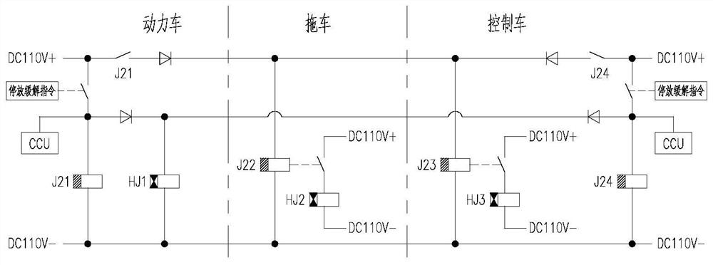
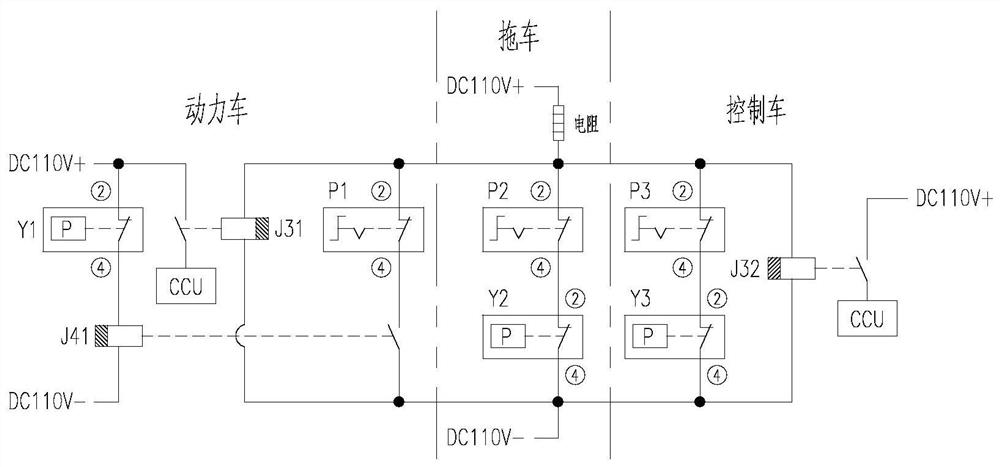
[0045] see Figure 1-Figure 5 A parking brake control system for a rail transit vehicle includes a parking control circuit, a parking loop and a state feedback circuit. The parking control circuit further includes a parking application control circuit and a parking mitigation control circuit.
[0046] Such as figure 1As shown, the parking application control circuit includes a first parking application switch located in the power vehicle, a first relay J11, a first parking unit, a second relay J12 located in the trailer, a second parking unit, and a control vehicle. The second parking application switch, the third relay J13, the fourth relay J14 and the third parking unit inside.
[0047] The coil of the first relay J11, the coil of the second relay J12, the coil of the third relay J13, and the coil of the fourth relay J14 are connected in parallel.
[0048] The first parking application switch is connected in series with the coil of the first relay J11, and the second park...
Embodiment 2
[0106] This embodiment provides a rail transit vehicle, including a power vehicle, a trailer and a control vehicle. This embodiment takes 1 power vehicle + 1 trailer + 1 control vehicle as an example. The actual car group formation may be 1 power car + 7 trailers + 1 control car, 1 power car + 18 trailers + 1 power car, 1 power car + 7 trailers + 1 control car + 1 Control car + 7 trailers + 1 power car, etc.
[0107] The rail transit vehicle in this embodiment is equipped with the rail transit vehicle parking brake control system in Embodiment 1.
Embodiment 3
[0109] This embodiment provides a parking brake control method for a rail transit vehicle, which is used to control the parking brake system of the power-concentrated EMU in Embodiment 1, and the method includes:
[0110] When the power car receives the parking application command, the first parking application switch is closed, and the feedback power car command state is applied; when the power car receives the parking relief command, the first parking release switch is closed, and the feedback power car command state is relief;
[0111] When the control car receives the parking application command, the second parking application switch is closed, and the command status of the feedback control car is marked as applied; when the control car receives the parking release command, the second parking release switch is closed, and the feedback control car command status is marked as ease;
[0112] When the contacts of the tenth relay and the eleventh relay are both disconnected, th...
PUM
 Abstract
Description
Claims
Application Information
 - R&D Engineer
- R&D Manager
- IP Professional
- Industry Leading Data Capabilities
- Powerful AI technology
- Patent DNA Extraction
Browse by: Latest US Patents, China's latest patents, Technical Efficacy Thesaurus, Application Domain, Technology Topic, Popular Technical Reports.
© 2024 PatSnap. All rights reserved.Legal|Privacy policy|Modern Slavery Act Transparency Statement|Sitemap|About US| Contact US: help@patsnap.com