
Electric assist device for a bicycle

A technology for auxiliary equipment and bicycles, which is applied to vehicle components, vehicle gearboxes, rider drives, etc., and can solve the problems of incomplete disassembly of the pedal shell and inability to remove the shaft of the pedal assembly axially, etc.

Pending Publication Date: 2021-12-28
马威克集团公司
View PDF12 Cites 0 Cited by
  • Summary
  • Abstract
  • Description
  • Claims
  • Application Information

AI Technical Summary

Problems solved by technology

[0027] Currently, in all known assist systems, it is not possible to simply axially remove the footrest assembly shaft without completely dismantling the footrest housing

Method used


Image

  • Electric assist device for a bicycle
  • Electric assist device for a bicycle
  • Electric assist device for a bicycle

Examples


Embodiment Construction

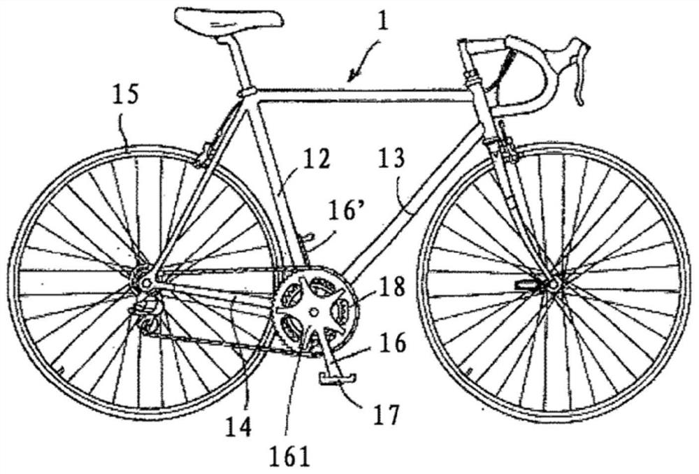
[0073] figure 1 A motor-assisted bicycle 1 incorporating an assistance system according to the invention is shown. In a known manner, such bicycles comprise a frame to which the two wheels are fixed. The rear wheel 15 provides the movement power and is driven by a pedal assembly (crankset) consisting of a pair of cranks 16 , 16 ′ and two pedals 17 . The right crank comprises a star 161 , the end of which is used to attach at least one toothed link 181 , 182 . A drive chain 19 mechanically connects one of said toothed links 181 , 182 to the rear wheel 15 .

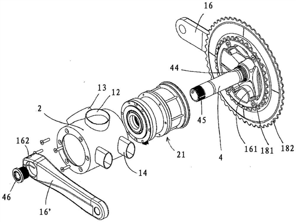
[0074] figure 2 An exploded view of an auxiliary device according to a first embodiment of the invention is shown. The pedal assembly housing 2 forms an integral part of the frame and connects a number of tubes forming the frame. The lower part of the dip tube 13, the lower part of the seat tube 12 and the front end of the dropout 14 can be seen. A housing 21 housing a number of auxiliary equipment components will be...


PUM


Abstract

An assist device for a bicycle comprising a motor (3), a step-down gear (5), a free wheel (6) and a shaft (4) which rotates as one with a right crank (16, 161) and a left crank (16'); the motor (3) transmitting an assist torque to the shaft (4) by means of the free wheel (6); the device being designed to be received inside a pedal assembly casing (2); the shaft being rotatably mounted relative to the casing by means of two ball bearings (224, 234); the free wheel (6) consisting of a plurality of pieces (63, 61, 65) which are placed between the motor (3) and the shaft (4); the device further comprising a torque transmission ring (44, 44', 44", 44'") which allows one of the pieces of the free wheel (61, 65) to be secured to the shaft (4) or to one of the cranks (16, 16', 161); the transmission ring (44, 44', 44") being at least partially placed under one of the two ball bearings (224, 234). The torque transmission ring (44, 44', 44", 44'") produces a first mechanical connection with one of the pieces of the free wheel and a second mechanical connection with the shaft (4) or one of the cranks (16, 16', 161); at least one of these two mechanical connections can be released so as to withdraw the shaft (4). The transmission ring can be placed near the right crank (16, 161) or near the left crank (16'). The releasable mechanical connection may be the one which is located between the ring (44, 44') and one of the pieces (65) of the free wheel or the one which is located between the ring (44, 44') and the shaft (4) or the left crank (16').

Description

technical field [0001] The invention relates to a bicycle equipped with an electric assist motor. More specifically, the present invention relates to a device for transmitting torque between an auxiliary motor and a drive chain of a bicycle. Background technique [0002] Before talking more specifically about the problem solved by the present invention, it is appropriate here to recall a number of general features of electrically assisted bicycles. A particular feature of this type of bicycle is the need for two power transmission paths: the pedal assembly-wheel path, which transmits the torque generated by the rider, and the motor-wheel path. These two drive paths need to be able to overlap, since theoretically and to meet regulations, the motor provides torque to the wheels only to the extent that the rider himself provides torque to the wheels via the pedal assembly. [0003] There are various configurations of electrically assisted bicycles, and the present invention r...

Claims


Application Information

Patent Timeline
IPC IPC(8): B62M6/55
CPCB62M6/55B62M11/145B62M11/14
Inventor J-P·梅卡B·亚历山大F-X·华特J·范丁
Owner 马威克集团公司
Learn More