
Combustible outgassing material lined altitude compensating rocket nozzle

a rocket nozzle and combustible material technology, applied in the field of bell nozzles, can solve the problems of increased costs, too heavy, too expensive, etc., and achieve the effect of increasing the lift carrying performance of the rocket engine, no additional weight, and relatively inexpensive combustible materials

Inactive Publication Date: 2009-05-28
THE AEROSPACE CORPORATION
View PDF0 Cites 7 Cited by
  • Summary
  • Abstract
  • Description
  • Claims
  • Application Information

AI Technical Summary

Benefits of technology

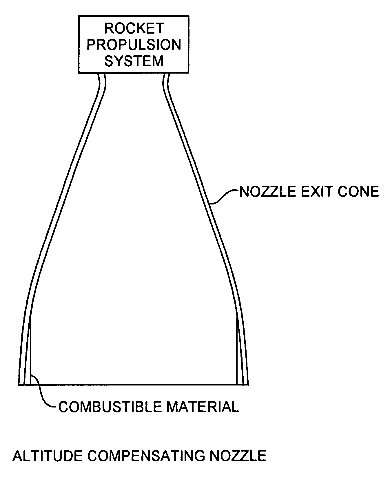
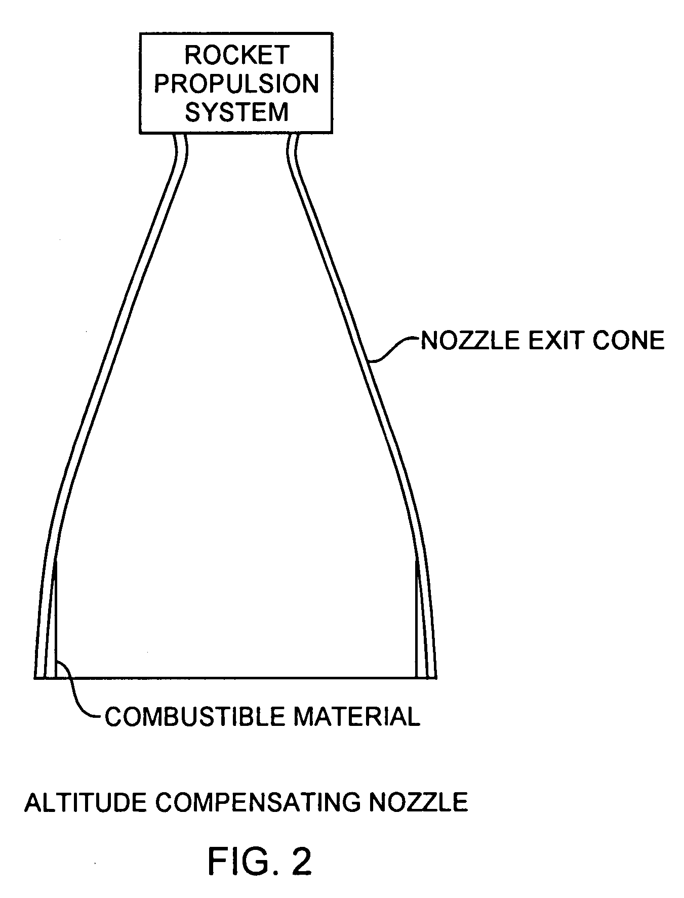
[0011]The present invention is directed to a relatively thin layer of combustible material disposed on the interior of the downstream aft portion of a rocket nozzle. The combustible material is an interior lining in the rocket nozzle that adjusts the exhaust pressure during the launch phase so as to match the exhaust pressure of the nozzle to atmospheric pressure over a large range of altitudes for increasing the lift carrying performance of a rocket engine without additional mechanical parts. The combustible material can be retrofitted into existing rocket nozzles. The combustible material is relatively inexpensive and carries no additional weight to high altitudes. In the preferred form, the combustible material is thinnest at a leading edge at a forward end and is thickest at the aft end of the nozzle. That is, the material preferably linearly tapers from a zero thickness at the forward end to be thickest at the aft end of nozzle. The leading edge of the material is located at the point along the vertical height dimension of the nozzle where the expansion ratio of the nozzle optimizes the engine thrust performance at the altitude of the launch site. The material thickness, position and taper are selected to optimize the lift carrying capability of the rocket propulsion system. In some applications, the taper may be nonlinear in thickness for particular rocket nozzles.

Problems solved by technology

For a launch off the ground, extremely high expansion ratio nozzles are not employed because the exhaust separates from the nozzle wall causing large side forces during launch.
Unfortunately, all of those mechanical designs have been considered too costly, too heavy, or too complicated to be incorporated in a practical launch vehicle.
Large heavy complicated mechanical systems that variably adjust the exit diameter of the nozzle will suffer from increased costs and reduced reliability of the rocket propulsion system.

Method used


Image

  • Combustible outgassing material lined altitude compensating rocket nozzle
  • Combustible outgassing material lined altitude compensating rocket nozzle
  • Combustible outgassing material lined altitude compensating rocket nozzle

Examples


Embodiment Construction

[0017]An embodiment of the invention is described with reference to the figures using reference designations as shown in the figures.

[0018]Referring to FIG. 2, a nozzle exit cone is part of rocket propulsion system including rocket propellant, not shown, and a rocket engine that includes a rocket motor, not shown, a combustion chamber, not shown, and an exhaust nozzle shown as the nozzle exit cone. The nozzle exit cone is simply referred to as the nozzle that is shown configured as a bell shaped rocket nozzle. Combustible material lines the interior cone surface of the nozzle preferably at the aft end of the exit cone as an altitude compensating nozzle. The combustible material can be adapted to be retrofitted into existing bell rocket nozzles. The combustible material is preferably a conventional solid rocket propellant, but may be any combustible material that provides an outgassing pressure when burned.

[0019]Referring to FIGS. 3A, 3B, 3C and 3D, the nozzle exit cone may have an e...


PUM


Abstract

A fixed sized bell rocket nozzle is lined with a layer of combustible material that is ignited during launch ignition and burns to outgas into the rocket exhaust for spatially variably confining the exhaust and perfecting an effective variably sized altitude compensating exhaust nozzle that maximizes lift during the launch of a spacecraft into orbit.

Description

FIELD OF THE INVENTION[0001]The invention relates to the field of rocket engines and bell nozzles. More particularly, the present invention relates to a bell rocket nozzle for maximizing lift capability during launch of a spacecraft.BACKGROUND OF THE INVENTION[0002]A rocket propulsion system is used to lift and propel spacecraft with a payload into space. The rocket propulsion system includes a rocket engine powered by rocket engine propellant to produce a gaseous exhaust providing necessary thrust to lift the spacecraft into orbit. A rocket engine includes a rocket motor, a combustion chamber and an exhaust nozzle. Rocket engine propellant is burned in the combustion chamber to produce the exhaust that may exit through the nozzle. The rocket propulsion system produces thrust by generating pressures in the combustion chamber and nozzle. The exhaust thrust pushes and hence lifts the launch vehicle off the surface of the earth into orbit.[0003]One type of rocket engine nozzle is the b...

Claims


Application Information

Patent Timeline
Patent Type & Authority Applications(United States)
IPC IPC(8): F02K9/97F02K9/08
CPCF02K9/14F02K9/974F02K9/34
Inventor HAWKINS, GARY F.MURDOCK, JOHN W.
Owner THE AEROSPACE CORPORATION
Learn More