
Rotor air refueling pod

A kind of aerial refueling and rotor technology, which is applied in the direction of rotorcraft, affecting the air flow flowing through the surface of the aircraft, transportation and packaging, etc., can solve the irregular swing movement of the refueling drogue, the impact of the flight safety of the refueling aircraft and the refueling aircraft, The refueling pod has no visual and radar system problems, and achieves the effects of increasing refueling speed, flexible aerial refueling, and improving refueling efficiency

Pending Publication Date: 2022-01-04
陕西北斗金箭航空科技有限公司
View PDF0 Cites 1 Cited by
  • Summary
  • Abstract
  • Description
  • Claims
  • Application Information

AI Technical Summary

Problems solved by technology

[0005] (1) The drogue sleeves of the refueling pod are basically in the form of floating, allowing the receiving machine to aim and dock. Affected by the atmosphere and eddy currents, the refueling drogue will produce a certain degree of irregular swing movement, and the receiving machine cannot Make an effective docking
[0006] (2) There is no vision and radar system on the existing refueling pod, which cannot meet the requirements of fast and accurate docking
[0007] (3) The existing refueling pod cannot quickly, safely and accurately connect the refueling machine and the refueling machine
[0008] (4) The existing refueling pod has relatively high requirements on the control of the oil receiver. If it cannot be docked safely and timely, it will have a certain impact on the flight safety of the tanker and the oil receiver

Method used


Image

  • Rotor air refueling pod
  • Rotor air refueling pod
  • Rotor air refueling pod

Examples


Embodiment Construction

[0051] The present invention will be described in detail below in conjunction with the accompanying drawings and specific embodiments.

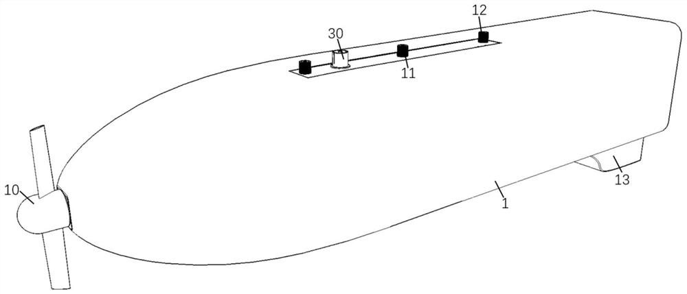
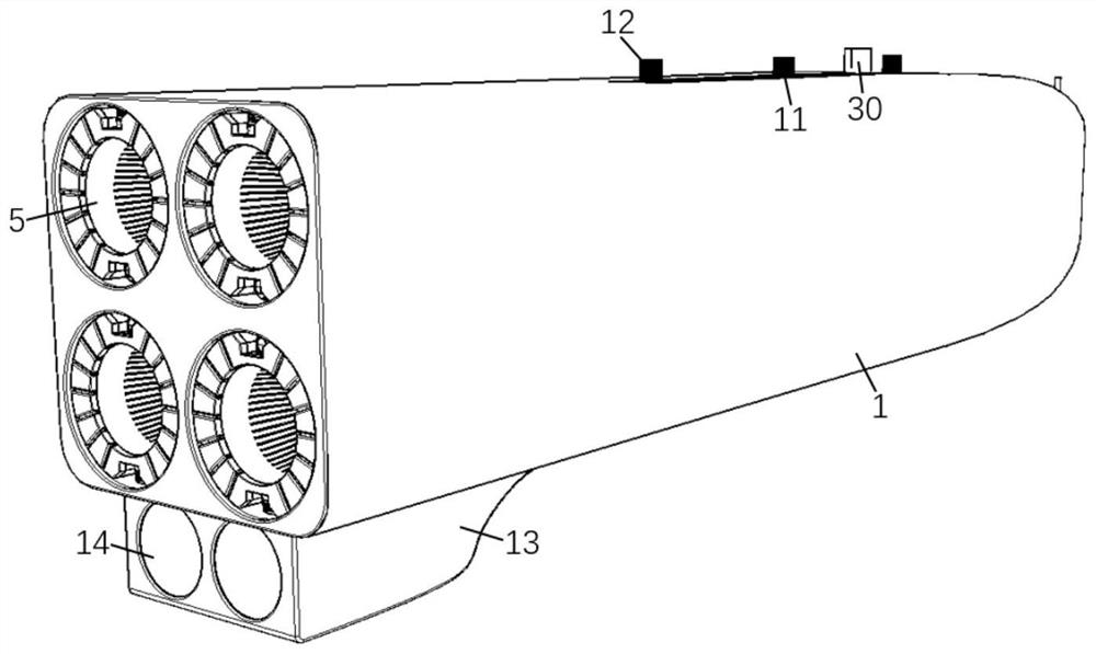
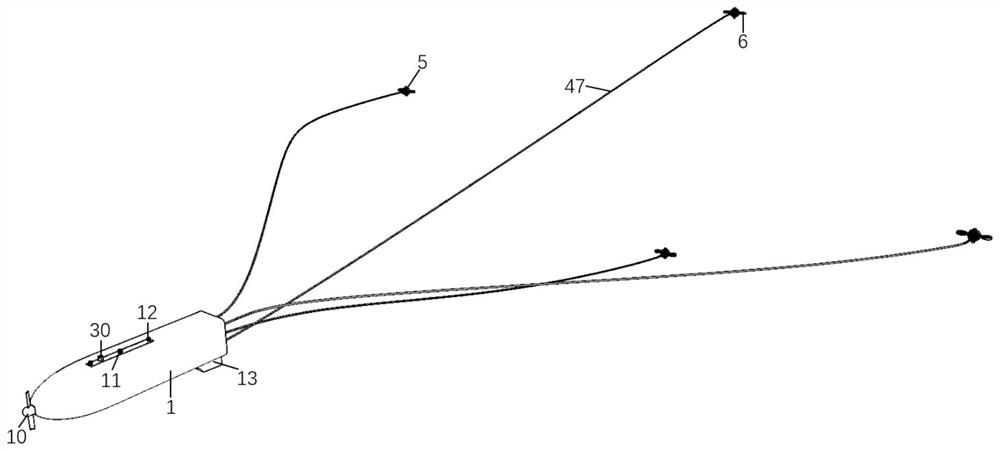
[0052] Such as Figure 1-12 As shown, a kind of rotor mid-air refueling pod of the present invention comprises shell 1, and the oil delivery system 3, refueling system 4 and refueling drogue 5 that are connected sequentially are arranged in shell 1, also comprise refueling pod controller 7 and power supply Assembly 8, refueling drogue 5 is connected with rotor 6, and power supply assembly 8 is used to supply power for oil delivery system 3, refueling system 4, refueling drogue 5 and rotor 6;

[0053] A ram air turbine 10 is arranged at the front end of the housing 1, and the ram air turbine 10 is connected to the oil delivery system 3; There is a pod camera base 13, and a pod camera 14 is installed in the pod camera base 13;

[0054] The top of the housing 1 is provided with a refueling fuel supply port 30, a control interface 11, and a con...


PUM


Abstract

The invention discloses a rotor air refueling pod which comprises a shell, a ram-type air turbine is arranged at the front end of the shell, a refueling machine fuel supply port, a control interface and a connecting port are formed in the top of the shell, a pod camera base is arranged below the rear end of the shell, and a pod camera is installed on the pod camera base. An oil conveying system, a refueling system, a refueling taper sleeve, a rotor wing, a refueling pod controller and a power supply assembly are arranged in the shell. According to the rotor air refueling pod, under the condition that normal refueling can be guaranteed, refueling operation can be conducted on more aircrafts, the taper sleeve is provided with the rotor, the refueling operation process can be faster and more intelligent, and the refueling operation efficiency can be improved.

Description

technical field [0001] The invention belongs to the technical field of aerial refueling devices, in particular to a rotor aerial refueling pod. Background technique [0002] The emergence of aerial refueling technology and aerial refueling aircraft has solved the problem of improving the flight range and airborne time of the aircraft on the premise of ensuring the aircraft's load and flight performance. [0003] Today's mainstream tankers are basically converted from passenger planes and transport planes. Tankers modified from such large aircraft have the advantages of long flight distances, a large amount of fuel that can be carried, and can provide refueling for multiple receivers at the same time. However, this type of large aircraft has higher requirements on the take-off airport, its own size is too large, the target is obvious, it is easy to be targeted, restricted by the modification platform, and the number is scarce. [0004] The current refueling pod has the follo...

Claims


Application Information

Patent Timeline
Patent Type & Authority Applications(China)
IPC IPC(8): B64D39/00B64D39/02B64D47/00B64D47/08B64C27/08B64C1/30
CPCB64D39/00B64D39/02B64D47/00B64D47/08B64C27/08B64C1/30
Inventor 王学锋武成菲刘丹
Owner 陕西北斗金箭航空科技有限公司
Learn More