Four-synchronous parallelogram transmission roller shutter rotary wing unmanned aerial vehicle

A parallelogram, unmanned aerial vehicle technology, applied in the directions of unmanned aerial vehicles, fuselage, aircraft, etc., can solve the problems of large forward resistance, low aerodynamic efficiency, large energy consumption, etc., to achieve reduced resistance, low production cost, The effect of improving aerodynamic efficiency

Pending Publication Date: 2022-01-11
GLOBAL INST OF SOFTWARE TECH
View PDF5 Cites 0 Cited by
  • Summary
  • Abstract
  • Description
  • Claims
  • Application Information

AI Technical Summary

Problems solved by technology

However, since the rotor of the rotorcraft is stationary relative to the central axis of the rotor, the forward resistance is relatively large, so the energy consumption is large, the aerodynamic efficiency is low, and it is difficult to fly with high power and long endurance

Method used


Image

  • Four-synchronous parallelogram transmission roller shutter rotary wing unmanned aerial vehicle
  • Four-synchronous parallelogram transmission roller shutter rotary wing unmanned aerial vehicle
  • Four-synchronous parallelogram transmission roller shutter rotary wing unmanned aerial vehicle

Examples


Embodiment 1

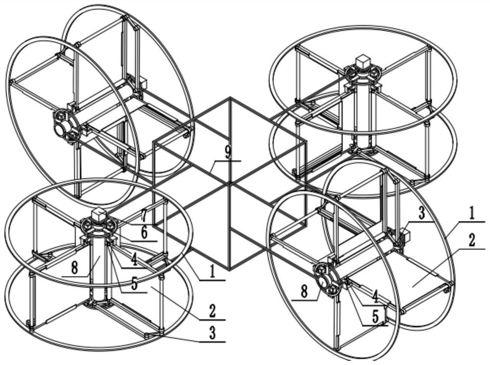
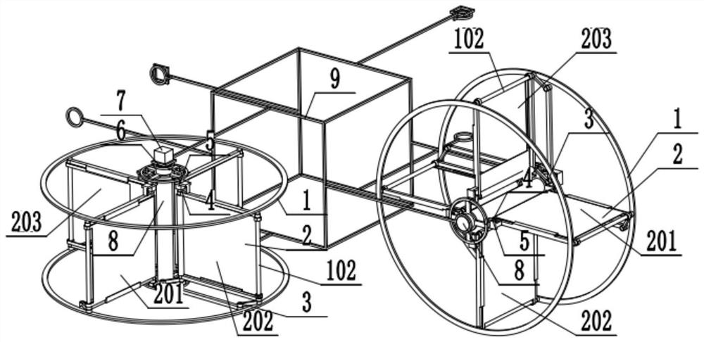
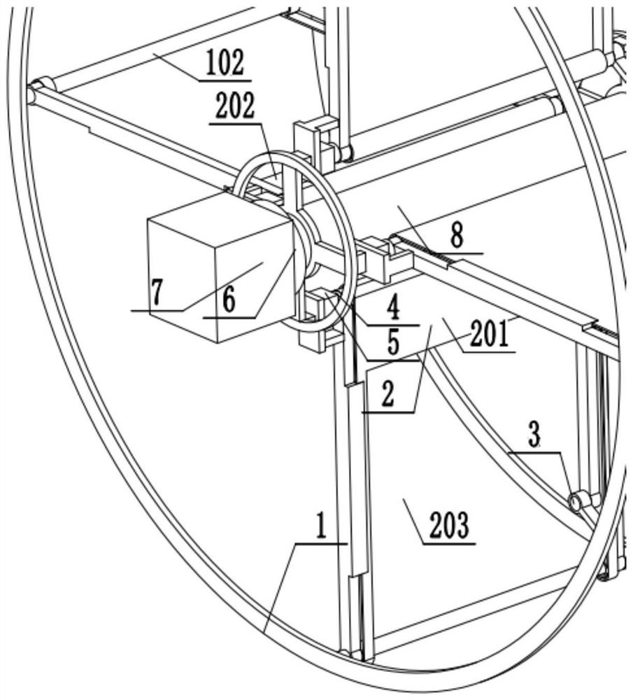
[0022] Example 1: Combining figure 1 , figure 2 , image 3 , Figure 4 , Figure 5 and Figure 6, a high-voltage wire inspection drone using a four-synchronous parallelogram transmission rolling shutter rotary wing drone. It includes a rotating curtain wing, a second speed reducer 6, a motor 7, a rotating shaft 8 and a fuselage frame 9, and the fuselage frame 9 is arranged symmetrically on both sides with two vertical rotating shafts 8, and the fuselage frame 9 is symmetrical front and rear Two horizontal rotating shafts 8 are arranged, and the four electric motors 7 arranged on the fuselage frame 9 respectively drive the four rotating shafts 8 to rotate continuously after being decelerated by four second reducers 6 arranged on the fuselage frame 9 , the four rotating curtains are respectively fixedly connected to the four rotating shafts 8, the left and right two rotating curtains are used to generate thrust, the front and rear two rotating curtains are used to generate...

Embodiment 2

[0023] Example 2: Combining figure 1 , figure 2 , image 3 , Figure 4 , Figure 5 and Figure 6 , a high-level fire-fighting drone that uses four synchronous parallelogram transmission rolling shutter rotary wing drones. It includes a rotating curtain wing, a second speed reducer 6, a motor 7, a rotating shaft 8 and a fuselage frame 9, and the fuselage frame 9 is arranged symmetrically on both sides with two vertical rotating shafts 8, and the fuselage frame 9 is symmetrical front and rear Two horizontal rotating shafts 8 are arranged, and the four electric motors 7 arranged on the fuselage frame 9 respectively drive the four rotating shafts 8 to rotate continuously after being decelerated by four second reducers 6 arranged on the fuselage frame 9 , the four rotating curtains are respectively fixedly connected to the four rotating shafts 8, the left and right two rotating curtains are used to generate thrust, the front and rear two rotating curtains are used to generate...


PUM


Abstract

The invention discloses a four-synchronous parallelogram transmission roller shutter rotary wing unmanned aerial vehicle which is characterized by comprising rotary shutter wings, rotary shafts, second speed reducers, motors and a fuselage frame; the two rotary shafts in the vertical direction are symmetrically arranged on the two sides of the fuselage frame, and the two horizontal rotary shafts are symmetrically arranged on the front portion and the rear portion of the fuselage frame; the four motors arranged on the fuselage frame are decelerated through the four second speed reducers arranged on the fuselage frame and then drive the four rotary shafts to rotate continuously; the four rotary curtain wings are fixedly connected to the four rotary shafts respectively, the left rotary curtain wing and the right rotary curtain wing are used for generating thrust, and the front rotary curtain wing and the rear rotary curtain wing are used for generating lift force; and each rotary curtain wing comprises a rotary frame and a roller shutter mounted in the rotary frame, and a parallelogram mechanism and a driving motor are further arranged in each rotary frame and used for controlling the roller shutter to be unfolded and folded.

Description

technical field [0001] The invention relates to the field of movable wing aircraft and flying robots, in particular to a four-synchronous parallelogram transmission rolling curtain rotary wing unmanned aerial vehicle. Background technique [0002] There are three flight types of aircraft: fixed wing, rotary wing and flapping wing, both of which are movable wings. [0003] Flapping wing flight is a flying method adopted by flying creatures in nature. It mainly uses the up and down flapping of the wings to generate lift and thrust at the same time. Flexibility, more suitable for performing flights around obstacles etc. For small-sized and low-speed aircraft flying under low Reynolds numbers, the unsteady lift generated by the flapping wing is much greater than the constant lift of the fixed wing; from the perspective of thrust, the propulsion efficiency of the flapping wing is higher than that of the propeller. At present, the research of flapping-wing aircraft mainly focuse...

Claims


Application Information

Patent Timeline
Patent Type & Authority Applications(China)
IPC IPC(8): B64C39/00B64C21/08B64C1/00
CPCB64C39/003B64C21/08B64C1/00B64C2001/0072B64U2101/00
Inventor 廖振强盛松梅杨静彭叶煜文崔联云徐浩丁荣晖邱明
Owner GLOBAL INST OF SOFTWARE TECH
Why Eureka
Try Eureka