Electromagnetic valve and using method thereof

A technology of solenoid valves and valves, applied in the field of solenoid valves, can solve problems such as economic loss of solenoid valves, easy blockage, poor circulation of solenoid valves, etc., and achieve the effect of preventing economic losses and convenient and stable use

Inactive Publication Date: 2022-01-11
瞿君
View PDF0 Cites 0 Cited by
  • Summary
  • Abstract
  • Description
  • Claims
  • Application Information

AI Technical Summary

Problems solved by technology

[0003] If the electromagnetic part of the existing solenoid valve is damaged during use, the solenoid valve will not be able to open normally, which will directly affect the circulation effect of the time, so that the solenoid valve that cannot be opened normally will cause a lot of economic losses, and the solenoid valve will not be opened normally when it is installed and used. At this time, due to the length error between the length of the pipeline and the connection situation, the space at the connection of the solenoid valve will be insufficient or the space is large, so that the solenoid valve cannot be installed normally, and the solenoid valve is easily blocked at the valve connection position when it is used, resulting in the flow of the solenoid valve. is not smooth, so there is an urgent need for a solenoid valve to solve the above problems

Method used


Image

  • Electromagnetic valve and using method thereof
  • Electromagnetic valve and using method thereof
  • Electromagnetic valve and using method thereof

Examples


Embodiment Construction

[0028] The following will clearly and completely describe the technical solutions in the embodiments of the present invention with reference to the accompanying drawings in the embodiments of the present invention. Obviously, the described embodiments are only some, not all, embodiments of the present invention. Based on the embodiments of the present invention, all other embodiments obtained by persons of ordinary skill in the art without making creative efforts belong to the protection scope of the present invention.

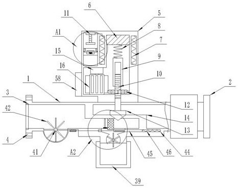
[0029] see Figure 1-6 , the present invention provides a technical solution: a solenoid valve, including a pipeline 1 and a valve housing 5, the upper end of the pipeline 1 is fixedly installed with a valve housing 5, and the right end of the pipeline 1 is provided with a compensation mechanism 56, the left side of the pipeline 1 and the right end of the compensation mechanism 56 are fixedly installed with a connecting valve 2, and several installation holes ...


PUM


Abstract

The invention discloses an electromagnetic valve and a using method thereof. The electromagnetic valve comprises a pipeline and a valve shell, the valve shell is fixedly installed at the upper end of the pipeline, a compensation mechanism is arranged at the right side end of the pipeline, and connecting valves are fixedly installed at the left side of the pipeline and the right side end of the compensation mechanism. During installation, a user moves an extension pipe to the left side or the right side, communication is guaranteed through a corrugated hose, meanwhile, movement of the extension pipe is guaranteed, the electromagnetic valve conforms to the installation position, when the extension pipe moves, a sliding block moves along a second sliding groove, after movement is completed, the user rotates a second screw rod, so that the second screw rod moves to the left side, a conical block is driven to move leftwards to extrude an extrusion block to move upwards until the extrusion block extrudes the position of the inner side wall of a second sliding groove, so that the position of the extension pipe is fixed, stable use after installation is facilitated, and the corrugated hose is protected by a sleeve in use after installation and is prevented from expanding and bursting when the pressure is too large.

Description

technical field [0001] The invention relates to the field of solenoid valve equipment, in particular to a solenoid valve and a method for using the same. Background technique [0002] Solenoid valve is an industrial equipment controlled by electromagnetic. It is an automatic basic component used to control fluid. It belongs to actuator and is not limited to hydraulic and pneumatic. It is used to adjust the direction, flow, speed and other parameters of the medium in the industrial control system. [0003] If the electromagnetic part of the existing solenoid valve is damaged during use, the solenoid valve will not be able to open normally, which will directly affect the circulation effect of the time, so that the solenoid valve that cannot be opened normally will cause a lot of economic losses, and the solenoid valve will not be opened normally when it is installed and used. At this time, due to the length error between the length of the pipeline and the connection situation...

Claims


Application Information

Patent Timeline
Patent Type & Authority Applications(China)
IPC IPC(8): F16K31/06F16L51/02F16L57/02F16K37/00F16K31/53F16K51/00B01D35/04B08B1/00
CPCF16K31/0655F16L51/025F16L57/02F16K37/0025F16K31/53F16K51/00B01D35/04B08B1/165
Inventor 瞿君
Owner 瞿君
Why Eureka
Try Eureka