a lighting device
A lighting device and installation surface technology, applied in the lighting field, can solve the problem that the lighting device is not easy to meet the complex and changeable shooting requirements, and achieve the effect of the best light mixing effect.
- Summary
- Abstract
- Description
- Claims
- Application Information
AI Technical Summary
Problems solved by technology
Method used
Image
Examples
Embodiment 1
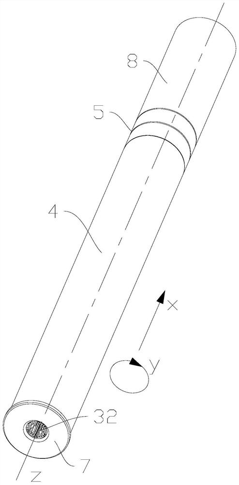
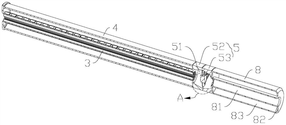
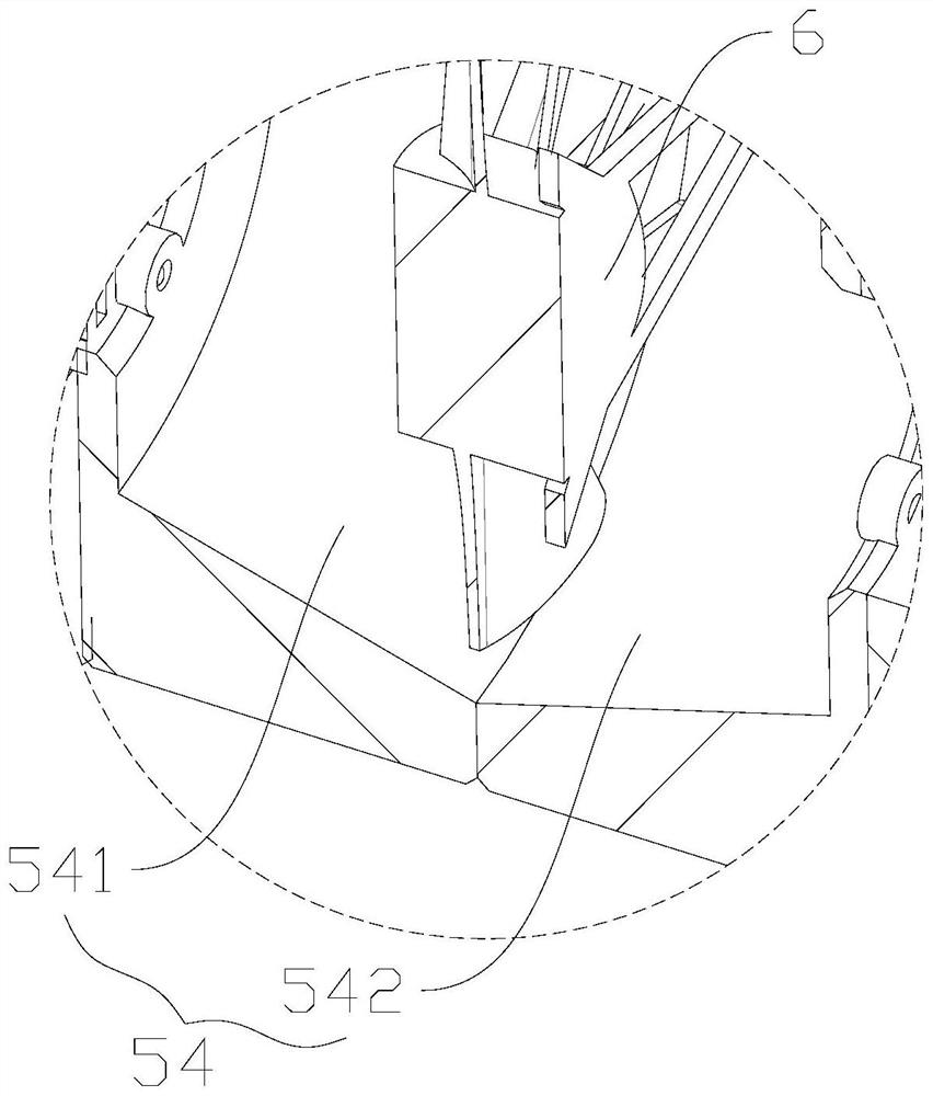
[0040] refer to Figure 1 to Figure 6 , Embodiment 1 of the present invention discloses a lighting device, which includes a base 3 , a first lamp bead 1 , a second lamp bead 2 and a diffusion cover 4 . base 3 along the first direction (eg figure 1 The direction shown by the arrow x) extends, and the base 3 is provided with a plurality of circles around the first direction (such as figure 1The direction indicated by the middle arrow y) is set and faces different installation surfaces 31 . The first lamp bead 1 is arranged on the installation surface 31 along the first direction, the color temperature of the second lamp bead 2 is different from that of the first lamp bead 1 , and the second lamp bead 2 is arranged at intervals from the first lamp bead 1 . On each mounting surface 31, the vertical distance from the end face of the first lamp bead 1 away from the mounting surface 31 to the center of the base 3 (such as Figure 4 shown in r1) is equal to the vertical distance fr...
Embodiment 2
[0089] see Figure 11 , Embodiment 2 of the present invention discloses a lighting device, the difference between Embodiment 2 and Embodiment 1 is:
[0090] The lighting device further includes a third lamp bead 9 , which is an RGB lamp bead, and the third lamp bead 9 is arranged between the first lamp bead 1 and / or the second lamp bead 2 on the same mounting surface 31 . It can be understood that the third lamp bead 9 may be a lamp bead in which three colors of R, G, and B are packaged together. Of course, optionally, three independent R chips, G chips, and B chips are also densely arranged together. A relatively complete third lamp bead 9 is relatively formed. Warm white light, cool white light and RGB lamp beads are used to combine multi-color light, which makes the light quality of the lighting device higher.
[0091] Specifically, when the first lamp beads 1 and the second lamp beads 2 are respectively located on different installation surfaces 31, the first lamp beads ...
Embodiment 3
[0094] see Figure 12 , the third embodiment of the present invention discloses a lighting device, the difference between the third embodiment and the first embodiment is:
[0095] The lighting device also includes a third lamp bead 9, the third lamp bead 9 is an RGB lamp bead, the third lamp bead 9 is located on a mounting surface 31 different from the first lamp bead 1 and the second lamp bead 2, the third lamp bead 9 is disposed on the installation surface 31 along the first direction. It can be understood that the third lamp bead 9 may be a lamp bead in which three colors of R, G, and B are packaged together. Of course, optionally, three independent R chips, G chips, and B chips are also densely arranged together. A relatively complete third lamp bead 9 is relatively formed. Warm white light, cool white light and RGB lamp beads are used to combine multi-color light, which makes the light quality of the lighting device higher.
[0096] Specifically, when the first lamp bea...
PUM
 Abstract
Description
Claims
Application Information
 - R&D
- Intellectual Property
- Life Sciences
- Materials
- Tech Scout
- Unparalleled Data Quality
- Higher Quality Content
- 60% Fewer Hallucinations
Browse by: Latest US Patents, China's latest patents, Technical Efficacy Thesaurus, Application Domain, Technology Topic, Popular Technical Reports.
© 2025 PatSnap. All rights reserved.Legal|Privacy policy|Modern Slavery Act Transparency Statement|Sitemap|About US| Contact US: help@patsnap.com


