Compound eye lens group and projection device using same

A fly-eye lens and projection device technology, applied in the field of projection, can solve the problems of numerous components, long optical path, and large size of the projection device, and achieve the effects of high light energy utilization, reduced volume, and miniaturization.

Inactive Publication Date: 2018-03-30
HISENSE VISUAL TECH CO LTD
View PDF4 Cites 17 Cited by
  • Summary
  • Abstract
  • Description
  • Claims
  • Application Information

AI Technical Summary

Problems solved by technology

[0003] However, in the traditional projection device, in order to shorten the distance of the optical path in the longitudinal direction, after using the fly-eye lens 20' to homogenize the light beam emitted by the light source 10', it is also necessary to set a special reflector 60' to change the direction of the optical path. This leads to a large number of components on the light transmission path, a long optical path, and a large projection device.

Method used


Image

  • Compound eye lens group and projection device using same
  • Compound eye lens group and projection device using same
  • Compound eye lens group and projection device using same

Examples


Embodiment Construction

[0039] Typical embodiments that embody the features and advantages of the present invention will be described in detail in the following description. It should be understood that the present invention is capable of various changes in different embodiments without departing from the scope of the present invention, and that the description and illustrations therein are illustrative in nature and not limiting. this invention.

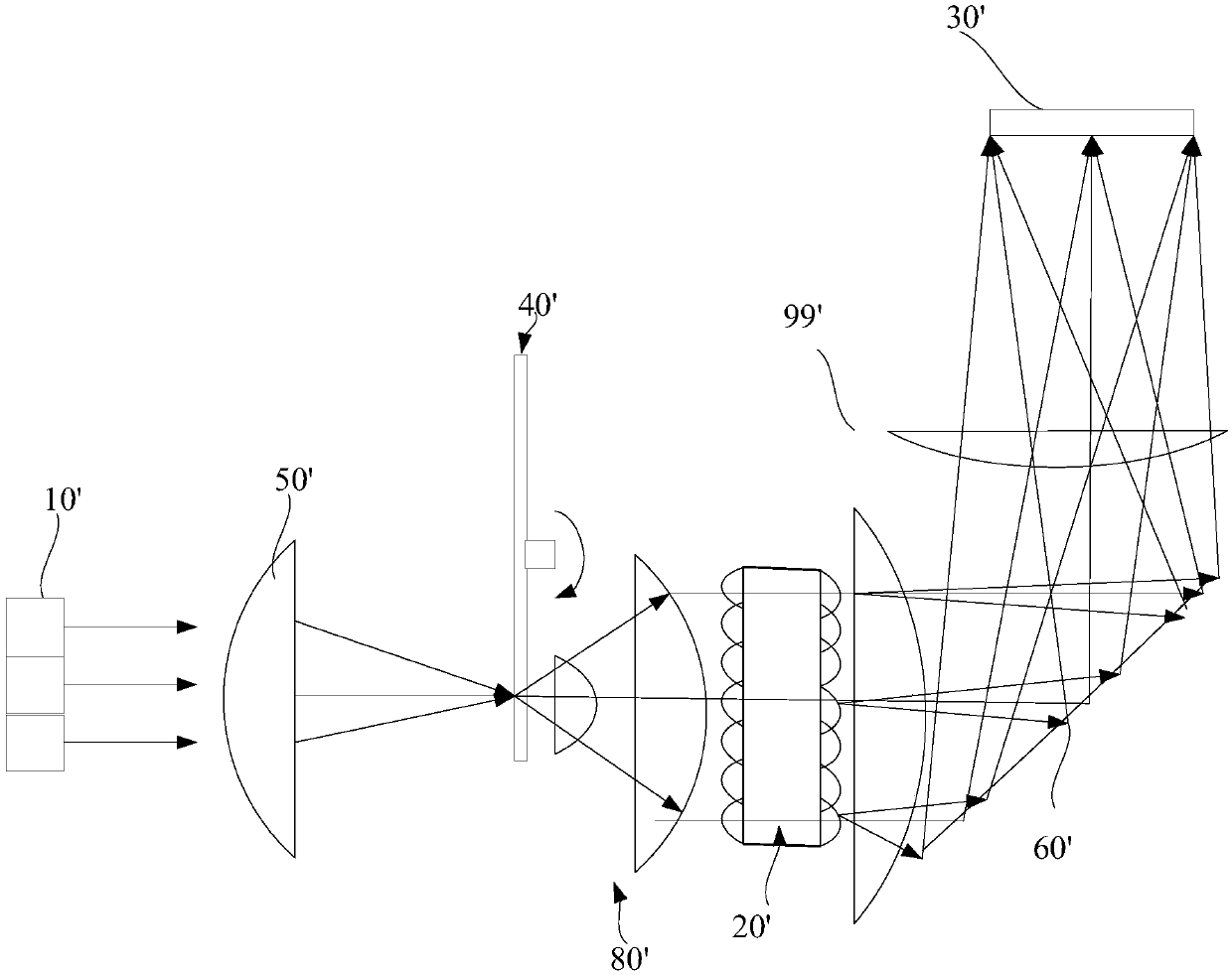
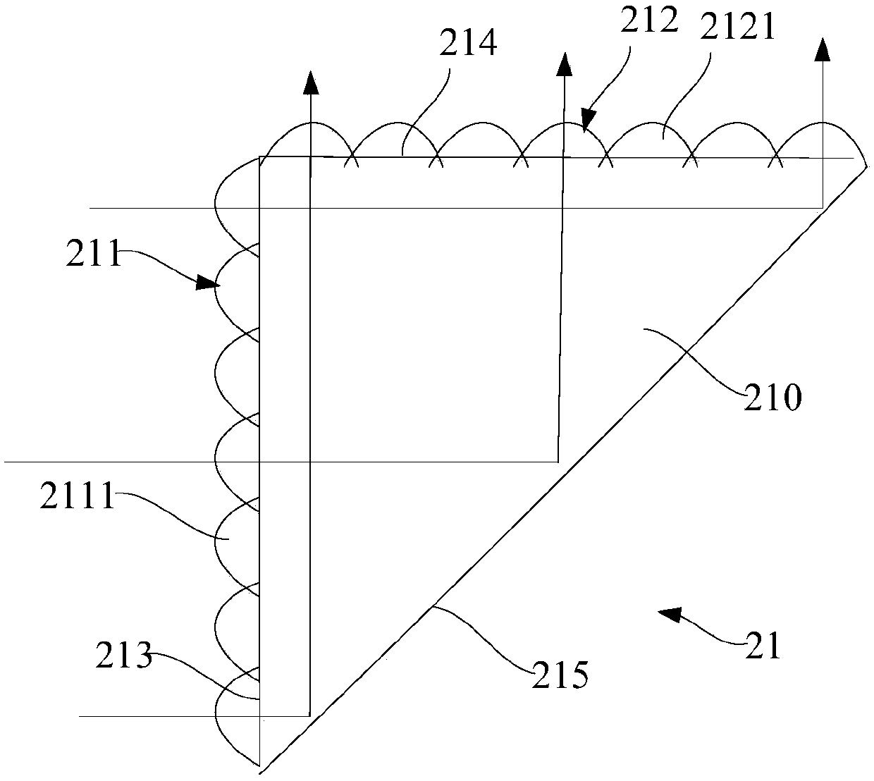
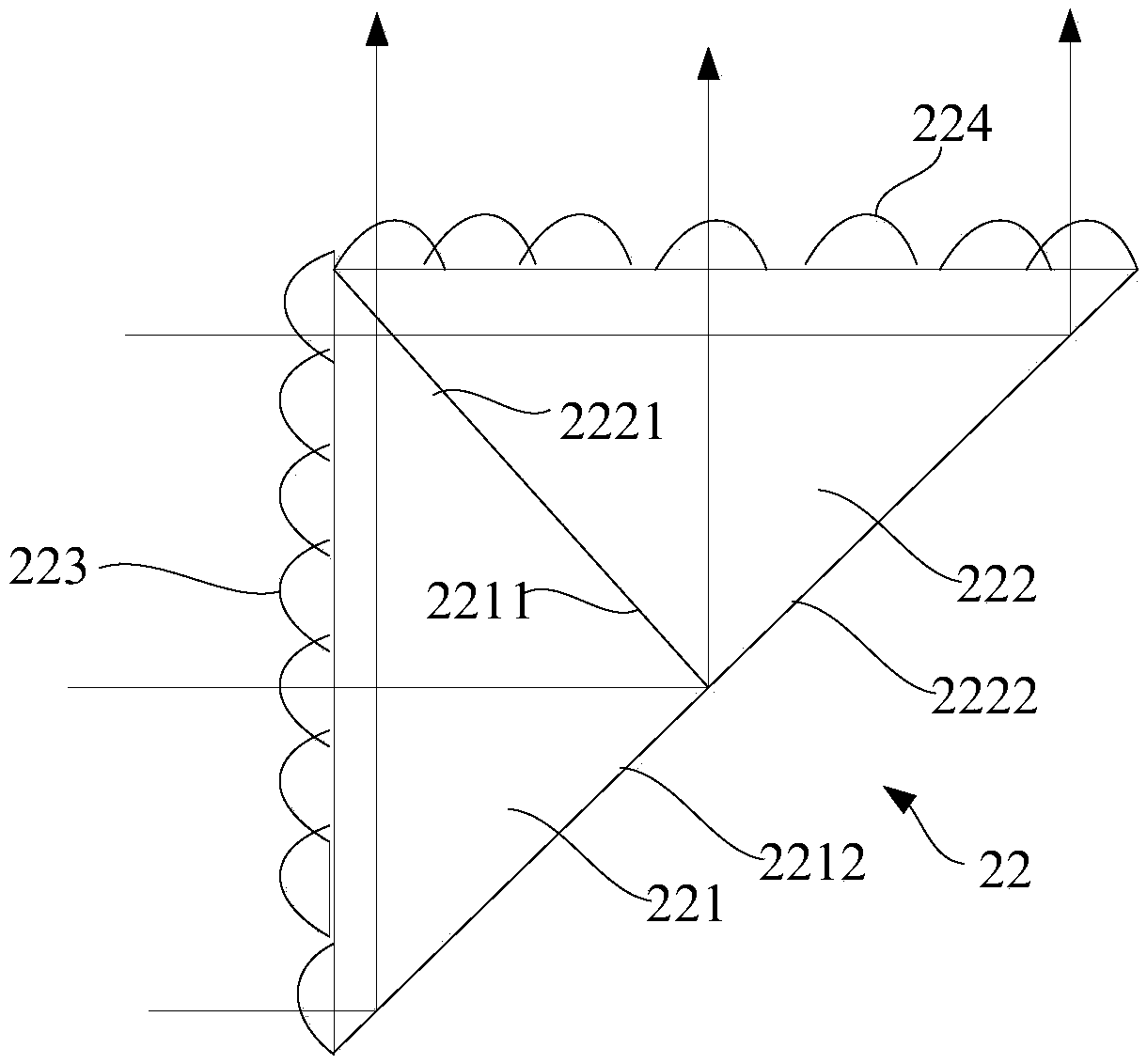
[0040] As mentioned above, in the traditional projection device, in order to shorten the distance of the optical path in the longitudinal direction, after the fly-eye lens homogenizes the light beam emitted by the light source, it is necessary to set up a special reflector to change the direction of the optical path. There are many parts on the transmission path, the optical path is long, and the volume of the projection device is large. To solve this problem, the present invention proposes a solution, that is, a fly-eye lens group is provided. The fly-eye...


PUM


Abstract

The invention provides a compound eye lens group and a projection device using same. The compound eye lens group comprises a light incident surface, a light reflecting surface and a light output surface, which are in triangle arrangement. A first microlens array is arranged on the light incident surface. The first microlens array enables an incident beam to be split into a plurality of beams of convergent light. The plurality of beams of convergent light converge into a plurality of point light sources on the light output surface after be reflected by the light reflecting surface. A second microlens array is arranged on the light output surface. The second microlens array is used for diffusing and outputting the light of the plurality of point light sources. The compound eye lens group andthe projection device using the same are simple in structure and small in size.

Description

technical field [0001] The invention relates to the field of projection, in particular to a fly-eye lens group and a projection device using the same. Background technique [0002] For the light source device technology of projection equipment, such as figure 1 As shown, conventionally, the illuminating device of a projection device includes a light source 10', a converging lens 50' and a fluorescent wheel 40'. The converging lens 50' converges the light beam emitted by the light source 10' and makes it incident on the fluorescent wheel 40'. A collimating lens group 80' is arranged behind the fluorescent wheel 40', and a double-sided fly-eye lens is placed on the collimating lens group 80'. The fluorescent wheel 40' is provided with a phosphor powder area and a transmission area, and as the fluorescent wheel rotates, the blue light emitted by the light source 10' is periodically irradiated on these two partitioned areas. The blue light irradiates the fluorescent powder ar...

Claims


Application Information

Patent Timeline
Patent Type & Authority Applications(China)
IPC IPC(8): G02B3/00G03B21/20
CPCG02B3/0062G03B21/204G03B21/2053G03B21/208
Inventor 王强
Owner HISENSE VISUAL TECH CO LTD
Why Eureka
Try Eureka