Photovoltaic component solder strip retro reflective film

A photovoltaic module and reflective film technology, which is applied in the field of reflective film, can solve problems such as unsatisfactory reflective surfaces, cell fragments, and sunlight utilization, and achieve the effects of improving light energy utilization, increasing output power, and increasing area

Inactive Publication Date: 2017-02-22
SUZHOU GOLDEN STAR ELECTRONICS TECH CO LTD
View PDF3 Cites 24 Cited by
  • Summary
  • Abstract
  • Description
  • Claims
  • Application Information

AI Technical Summary

Problems solved by technology

In order to ensure reliable welding between the ribbon and the battery and prevent corrosion of the ribbon, the surface of the ribbon is coated with a tin layer. When the sunlight hits the surface of the ribbon, the tin layer will directly reflect the sunlight, and this part of the sunlight cannot Utilized by battery panels, resulting in a waste of light energy
[0003] Some solder strips have stripes on the body to reflect light, but the base material of the solder strips is copper, and the stripe structure is difficult to achieve a microstructure during processing. The reflective surface is not ideal. After tin coating, the thickness of the tin layer is likely to be uneven Uniform, easy to cause fragments of the cell, the price of tin raw materials is high, too thick will cause serious waste
[0004] In the patent literature with the publication number CN103413861A, a reflective film for photovoltaic modules is disclosed. The surface layer is provided with a prism-shaped microstructure layer, which is simple in structure and low in cost, and can improve the light energy utilization rate of photovoltaic modules. The ridgeline of the prism structure is along the length of the ribbon, and the reflected light will only be reflected to a local area of ​​the cell, which does not make full use of the entire cell

Method used


Image

  • Photovoltaic component solder strip retro reflective film
  • Photovoltaic component solder strip retro reflective film
  • Photovoltaic component solder strip retro reflective film

Examples


Embodiment Construction

[0034] The following will clearly and completely describe the technical solutions in the embodiments of the present invention with reference to the accompanying drawings in the embodiments of the present invention. Obviously, the described embodiments are only some, not all, embodiments of the present invention. Based on the embodiments of the present invention, all other embodiments obtained by persons of ordinary skill in the art without creative efforts fall within the protection scope of the present invention.

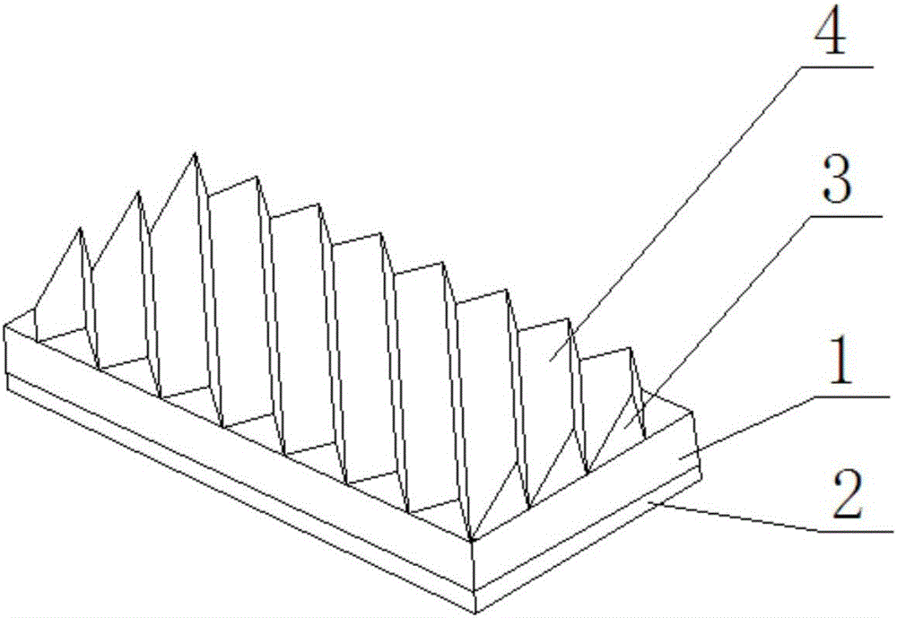
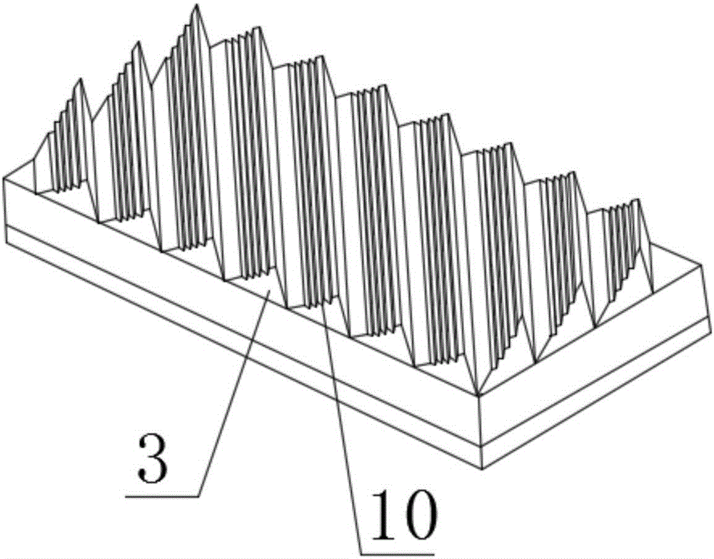
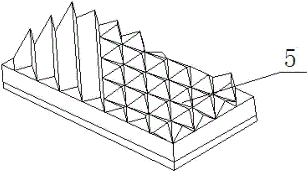
[0035] In order to achieve the purpose of the present invention, as figure 1 As shown, an embodiment of the present invention is: a reflective film used on the photovoltaic module soldering tape, including a base material 1, a back adhesive layer 2, a microprism layer 3, a reflective layer 4, and the back adhesive layer 2 is set On the lower surface of the substrate 1, the microprism layer 3 is a plurality of microprism arrays, which are arranged on the upper surfa...


PUM

PropertyMeasurementUnit
widthaaaaaaaaaa

Abstract

The invention provides a photovoltaic component solder strip retro reflective film, including a base material, a back glue layer, a micro prism layer, a retro reflective layer, the back glue layer is provided on the lower surface of the base material, the micro prism layer is a multi micro prism array, and is provided on the upper surface of the base material, the retro reflective layer covers the surface of the micro prism layer, the ridge line direction of the micro prism and the length direction of the base material form a 15 DEG- 65 DEG angle setting. Compared to prior art, the ridge line direction of the micro prism and the length direction of the base material form an angle setting, which can augment the area of the reflecting surface, also enables the reflected light to recycle a larger surface of the cell slice, increases the utilization rate of light source, and increases the output power of the photovoltaic component.

Description

technical field [0001] The invention relates to a reflective film, in particular to a reflective film used on a photovoltaic module welding ribbon. Background technique [0002] Photovoltaic ribbons are used in the connection between photovoltaic module cells, and play an important role in conducting electricity and collecting electricity. In order to ensure reliable welding between the ribbon and the battery and prevent corrosion of the ribbon, the surface of the ribbon is coated with a tin layer. When the sunlight hits the surface of the ribbon, the tin layer will directly reflect the sunlight, and this part of the sunlight cannot Utilized by the battery board, resulting in a waste of light energy. [0003] Some solder strips have stripes on the body to reflect light, but the base material of the solder strips is copper, and the stripe structure is difficult to achieve a microstructure during processing. The reflective surface is not ideal. After tin coating, the thicknes...

Claims


Application Information

Patent Timeline
Patent Type & Authority Applications(China)
IPC IPC(8): H01L31/054G02B5/124
CPCY02E10/52H01L31/0547G02B5/124
Inventor 张丽萍高瑞丁晶
Owner SUZHOU GOLDEN STAR ELECTRONICS TECH CO LTD
Why Eureka
Try Eureka