Light guiding plate and backlight module employing the same

Active Publication Date: 2007-07-12
TSINGHUA UNIV +1
View PDF5 Cites 18 Cited by
  • Summary
  • Abstract
  • Description
  • Claims
  • Application Information

AI Technical Summary

Benefits of technology

[0007]A light guiding plate according to a preferred embodiment includes an light incident surface, a light emitting surface adjacent to the light incident surface, and a bottom surface opposite to the light emitting surface. The light incident surface includes at least one row of first grooves and at least one row of second grooves, the first grooves being co

Problems solved by technology

However, backlight devices employing cold cathode fluorescent lamps have the disadvantages of high energy consumption, low uniformity of brightness, poor purity of white light, and high cost.
In addition, after being used for a period of time, the brightness of a CCFL tends to be

Method used


Image

  • Light guiding plate and backlight module employing the same
  • Light guiding plate and backlight module employing the same
  • Light guiding plate and backlight module employing the same

Examples


first embodiment

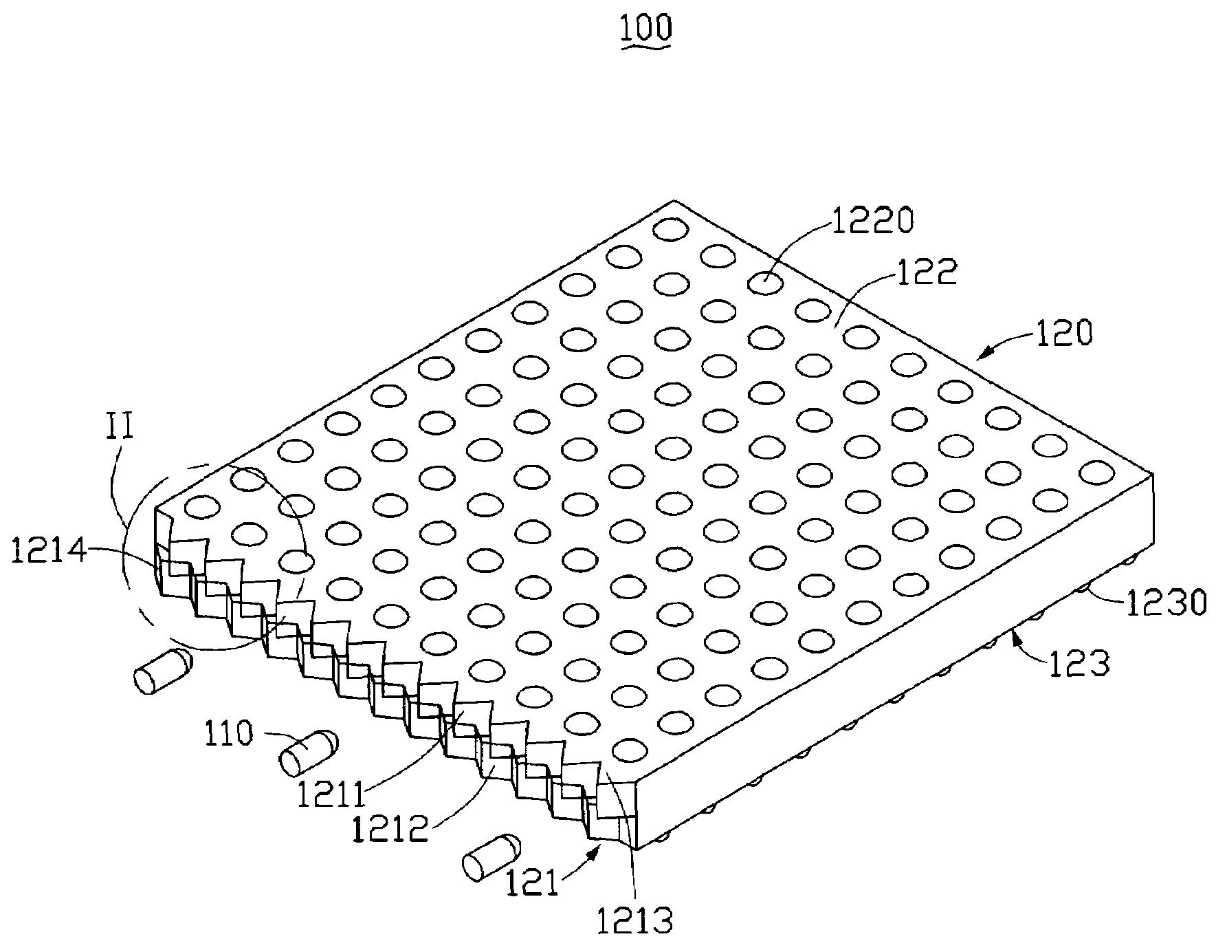
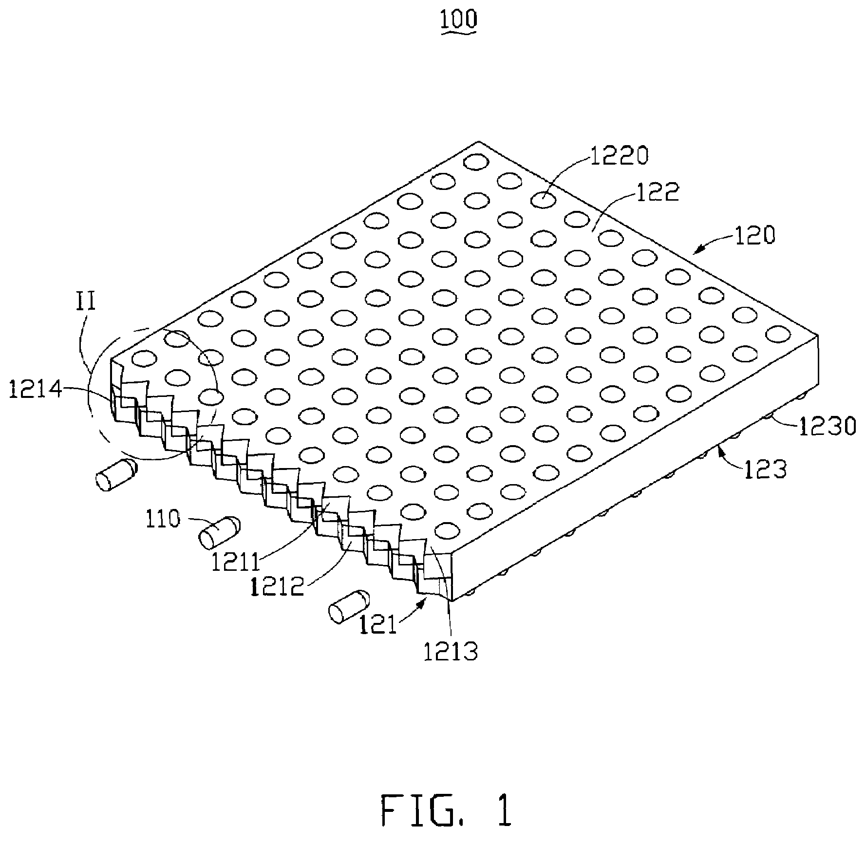
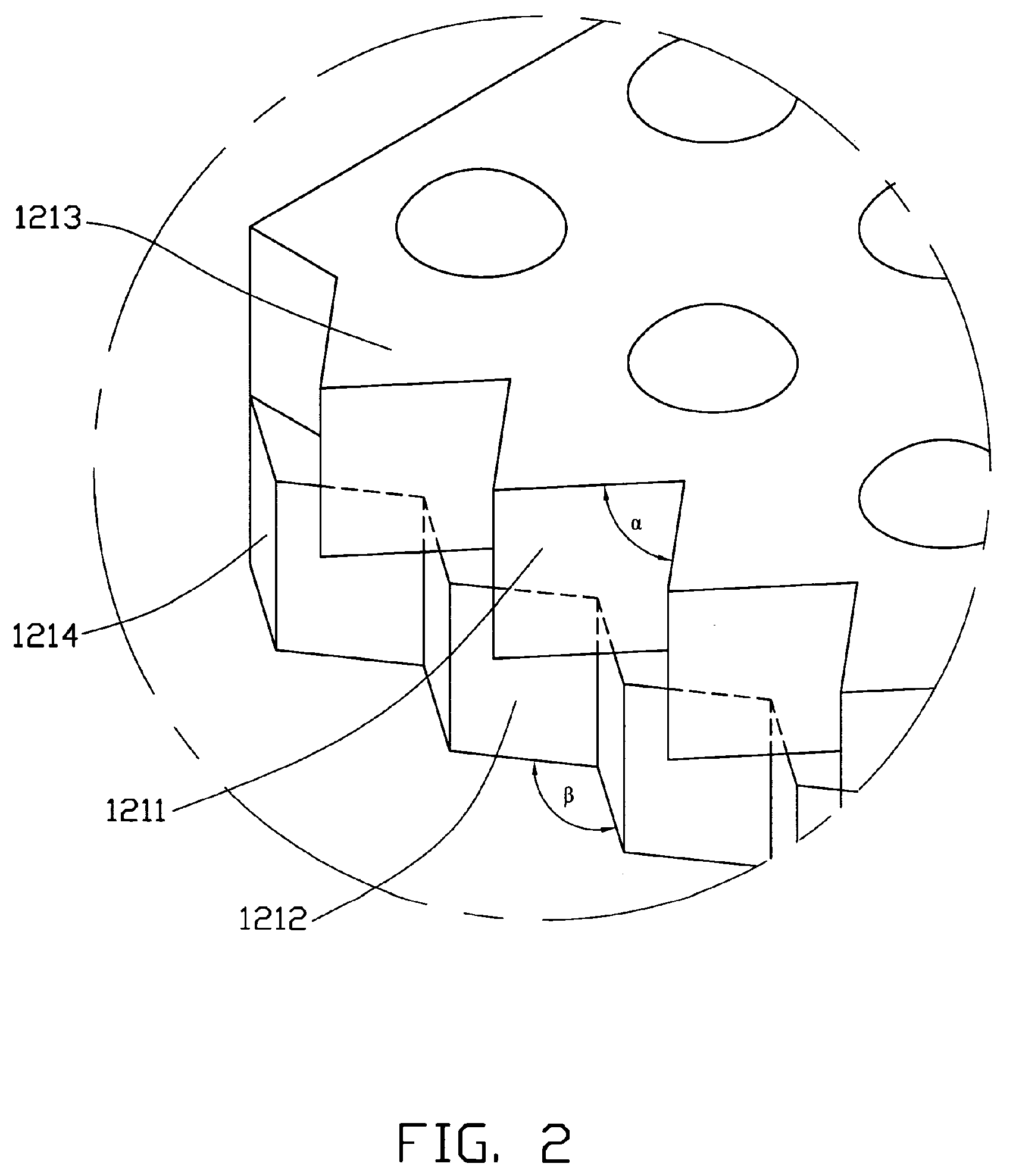
[0029]Referring to FIGS. 3 and 4, a backlight module 200 in accordance with a second preferred embodiment is shown. The backlight module 200 is similar to the backlight module 100 of the However, in the backlight module 200, except that at least one row of parallel first V-shaped grooves 2211 is defined in a light incident surface 121 of a light guiding plate 220, and at least one row of aligned second V-shaped grooves 2212 is defined in the light incident surface 121 of the light guiding plate 220. In this exemplary embodiment, there are three rows of first V-shaped grooves 2211, and two rows of second V-shaped grooves 2212. Each of the first V-shaped grooves 2211 is aligned along a vertical direction. Further, each first V-shaped groove 2211 in any of the rows of first V-shaped grooves 2211 is aligned with a corresponding first V-shaped groove 2211 in each of the other rows of first V-shaped grooves 2211. Each of the second V-shaped grooves 2212 is aligned along a horizontal dire...

second embodiment

[0033]In summary, the light guiding plate 120, 220 in accordance with the first or second embodiment can efficiently increase the brightness and the uniformity of light that it outputs. This makes the light guiding plate 120, 220 advantageous for use in the backlight modules 100, 200, other kinds of backlight modules, liquid crystal displays, etc.


PUM


Abstract

A light guiding plate (120) includes a light incident surface (121), a light emitting surface (122) adjacent to the light incident surface, and a bottom surface (123) opposite to the light emitting surface. The light incident surface includes at least one row of first grooves (1211) and at least one row of second grooves (1212). The first grooves is configured for increasing a range of incident angles in which light beams enter the light guiding plate via the light incident surface and thereby improving a brightness of the light guiding plate, and the second grooves is configured for complementing the functions of the first grooves thereby improving a uniformity of light output by the light guiding plate.

Description

1. FIELD OF THE INVENTION[0001]The present invention relates to light guiding plates and, more particularly, to a light guiding plate with high uniformity of output light and a backlight module employing the light guiding plate.2. DESCRIPTION OF RELATED ART[0002]Nowadays, liquid crystal displays which have different sizes are in widespread use for different applications, such as TVs, liquid crystal projectors, mobile telephones, personal digital assistants (PDAs), etc. Because the liquid crystal of a liquid crystal display cannot itself emit light, a light source must be utilized to illuminate the liquid crystal to enable images to be displayed. The light source may be ambient light or a light source device provided with the liquid crystal display. The light source device is commonly called a backlight source, since it is usually configured behind a liquid crystal panel of the liquid crystal display. A combination of all components behind the liquid crystal panel, including the ligh...

Claims


Application Information

Patent Timeline
IPC IPC(8): F21V7/04
CPCG02B6/0043G02B6/0016
Inventor YANG, XING-PENGYAN, YING-BAIJIN, GUO-FAN
Owner TSINGHUA UNIV
Why Eureka
Try Eureka