Flash lamp control system and method

A technology for controlling systems and flashlights, applied to parts, optics, instruments, etc. of TV systems, which can solve problems such as waste, limited flash brightness of flashlights, and inability of batteries to provide driving current, so as to improve shooting effects and improve accuracy.

Active Publication Date: 2016-07-27
FU TAI HUA IND SHENZHEN +1
View PDF6 Cites 18 Cited by
  • Summary
  • Abstract
  • Description
  • Claims
  • Application Information

AI Technical Summary

Problems solved by technology

However, if the drive current of the flash is too high, more electric energy will be wasted, and the existing mobile terminal is limited by its own size, and its battery cannot provide a large enough drive current, resulting in limited flash brightness and poor photo exposure

Method used


Image

  • Flash lamp control system and method
  • Flash lamp control system and method
  • Flash lamp control system and method

Examples


Embodiment Construction

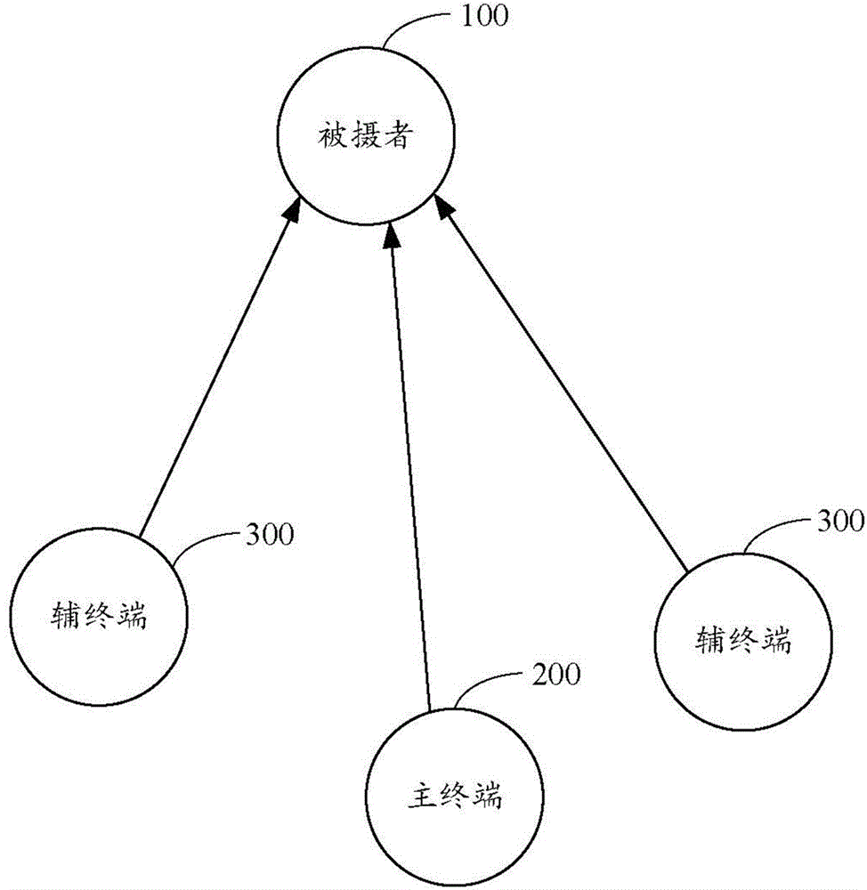
[0016] see figure 1 , is a schematic diagram of a subject 100 being photographed with supplementary light by a plurality of mobile terminals in an embodiment of the present invention. The mobile terminal may be a smart phone, a tablet computer, or the like. The multiple mobile terminals are located around a subject 100 , including a main mobile terminal (hereinafter referred to as the main terminal 200 ) and multiple auxiliary mobile terminals (hereinafter referred to as the auxiliary terminal 300 ). The main terminal 200 is used to take pictures of the subject 100 , and the multiple auxiliary terminals 300 are used to supplement light to the subject 100 synchronously with the main terminal 200 .

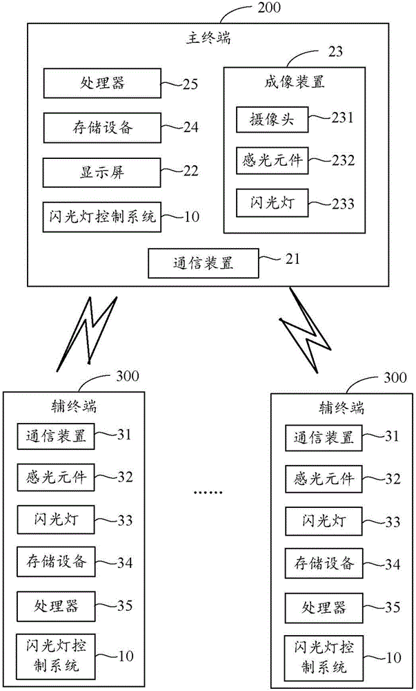
[0017] see figure 2 , is a schematic diagram of the operating environment of the flashlight control system 10 in an embodiment of the present invention. The flashlight control system 10 is installed and runs in the master terminal 200 and the plurality of slave terminals 300 . ...


PUM


Abstract

The invention provides a flash lamp control system and a method, which are applied to a master terminal and a plurality of slave terminals. The master terminal and the plurality of slave terminals are located around a to-be-photographed person. The flash lamp control system controls the master terminal and the plurality of slave terminals to respectively sense the optical parameters of the to-be-photographed person. Based on the optical parameters, the flash lamp driving current value and the flash duration of each terminal can be calculated. During the exposure photographing process, the flash lamp lighting conditions of the master terminal and the plurality of slave terminals are synchronously controlled, so that the sufficient amount of exposure is provided. According to the technical scheme of the flash lamp control system and the method, the light measuring accuracy is improved by arranging a plurality of mobile terminals around the to-be-photographed person. Meanwhile, based on the synchronous lighting-supplementing effect of the plurality of mobile terminals, the lighting brightness at a spot is improved. Therefore, the balance of the lighting brightness for the to-be-photographed person is ensured. As a result, the amount of exposure for the image photographing process is sufficient. The photographing effect is improved.

Description

technical field [0001] The present invention relates to the technical field of photographing by a mobile terminal, in particular to a flashlight control system and method. Background technique [0002] At present, most mobile terminals have a camera function, which brings convenience for users to take pictures. In order to obtain a better exposure effect in a photo under insufficient light conditions, a flashlight is usually added in the mobile terminal to flash to supplement the light. The magnitude of the driving current of the flashlight directly affects the exposure effect of the photos taken by the mobile terminal. However, if the drive current of the flash is too high, more electric energy will be wasted, and the existing mobile terminal is limited by its own size, and its battery cannot provide a large enough drive current, resulting in limited flash brightness and poor photo exposure. Contents of the invention [0003] In view of this, it is necessary to propose ...

Claims


Application Information

Patent Timeline
Patent Type & Authority Applications(China)
IPC IPC(8): H04N5/235G03B15/05
Inventor 周建闵许伯任庄志远林忠亿卢志德张书元
Owner FU TAI HUA IND SHENZHEN
Why Eureka
Try Eureka