
Lens capable of achieving multi-position illumination through single light source

A single light source and lens technology, which is applied to the parts of lighting devices, the optical aspects of lighting equipment, and light sources, can solve the problems of complex structure, many components, uneven brightness, etc., and achieve high luminous efficiency, convenient manufacturing, The effect of simple structure

Pending Publication Date: 2020-04-24
上海福宇龙汽车科技有限公司
View PDF0 Cites 0 Cited by
  • Summary
  • Abstract
  • Description
  • Claims
  • Application Information

AI Technical Summary

Problems solved by technology

At present, the cup holder atmosphere lights of similar products on the market are divided into two types: the first type, in the form of a lamp head, illuminates the inside of the cup holder from the small hole on the side wall of the cup holder. , the brightness is uneven; the second type is arranged on the upper edge of the cup holder in the form of a ring-shaped light guide strip. Each ring-shaped light guide strip needs 1-2 LED light sources. Generally, the cup holder of the whole vehicle has two cup slots. This requires 2-4 LED light sources. This type of cup holder ambient light has uniform brightness around the circle, but the structure is complex, there are many components, the processing of the light guide strip is difficult, and the overall cost remains high.

Method used


Image

  • Lens capable of achieving multi-position illumination through single light source
  • Lens capable of achieving multi-position illumination through single light source
  • Lens capable of achieving multi-position illumination through single light source

Examples


Embodiment Construction

[0022] The specific implementation manners of the present invention will be further described in detail below in conjunction with the accompanying drawings and embodiments. The following examples are used to illustrate the present invention, but should not be used to limit the scope of the present invention.

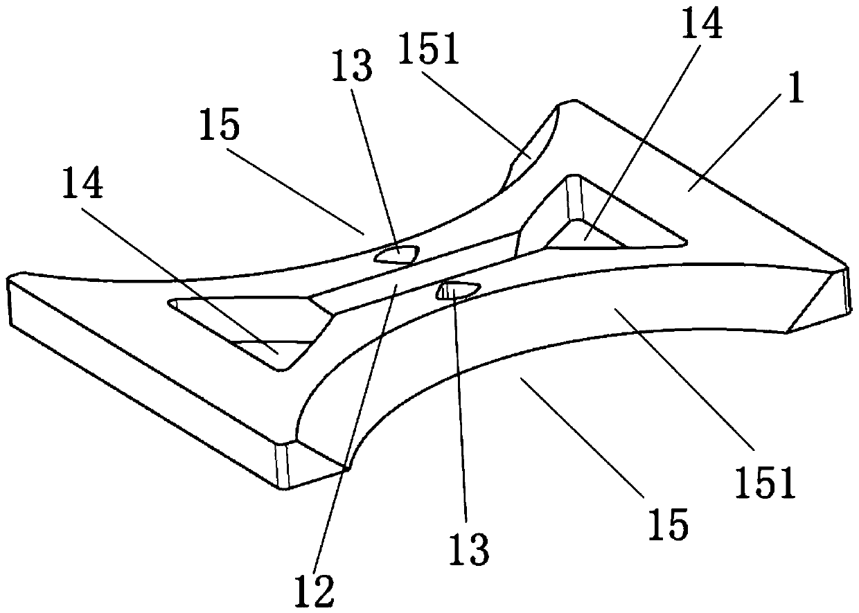
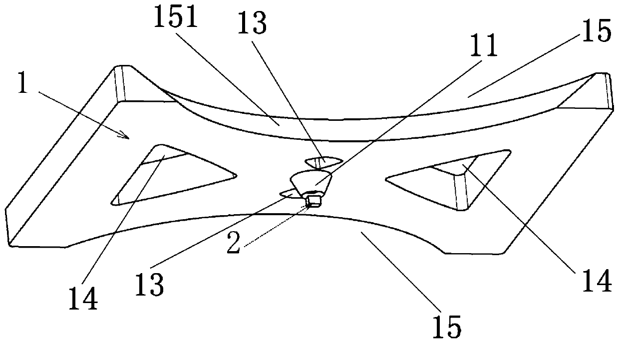
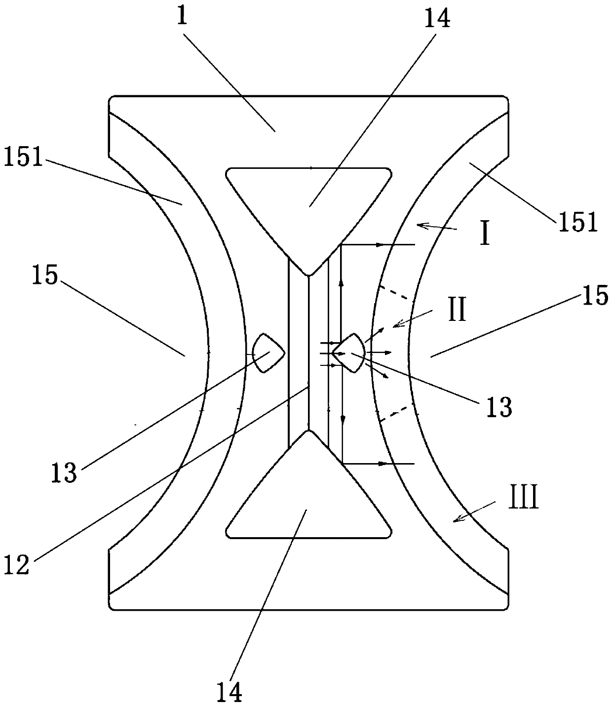
[0023] The structure of the lens that can realize multiple lighting with a single light source in the present invention is as follows: figure 1 and figure 2 As shown, the lens capable of realizing multiple illuminations with a single light source includes a lens body 1, the middle bottom of the lens body 1 is provided with a light-gathering mechanism 11, and the middle top of the lens body 1 is provided with symmetrically distributed V-shaped grooves 12; the lens body The top surface of 1 is also provided with two fan-shaped holes 13 symmetrically distributed on both sides of the V-shaped groove 12. The midpoint of the line connecting the two fan-shaped holes 13 vertic...


PUM

PropertyMeasurementUnit
Angleaaaaaaaaaa
Arc angleaaaaaaaaaa
Angleaaaaaaaaaa

Abstract

The invention discloses a lens capable of achieving multi-position illumination through a single light source. The lens comprises a lens body, wherein a light condensation mechanism is arranged at thebottom of the middle of the lens body, a V-shaped groove is formed in the top of the middle of the lens body, fan-shaped holes with arc-shaped surfaces deviating from the V-shaped groove are symmetrically formed in two sides of the V-shaped groove correspondingly, V-shaped holes are further symmetrically formed in the two ends of the V-shaped groove correspondingly, the vertex angles of the V-shaped holes coincide with the end of the V-shaped groove in a matched mode, arc-shaped grooves which are symmetrically distributed in the two sides of the V-shaped groove and matched with a cup are formed in the two sides of the lens body correspondingly, arc-shaped edges of the arc-shaped grooves are inclined arc faces inclining upwards, and the midpoint of the connecting line of the midpoints of the two inclined arc faces is perpendicularly overlapped with the light condensation mechanism. According to the lens, only one light source needs to be arranged at the position of the light condensation mechanism, light rays can be irradiated to the V-shaped groove in a concentrated mode through the light condensation mechanism and are symmetrically reflected to the two sides through the V-shapedgroove, and it is guaranteed that the two arc-shaped grooves have enough light rays for illumination.

Description

technical field [0001] The invention belongs to the technical field of lamps for vehicles, and in particular relates to a lens capable of realizing multiple lighting with a single light source. Background technique [0002] Cars generally have cup holders for placing water glasses, and ambient lights are set in the cup slots of the cup holders for eye-catching purposes. At present, the cup holder atmosphere lights of similar products on the market are divided into two types: the first type, in the form of a lamp head, illuminates the inside of the cup holder from the small hole on the side wall of the cup holder. This solution concentrates the light in a small area and has a small irradiation range , the brightness is uneven; the second type is arranged on the upper edge of the cup holder in the form of a ring-shaped light guide strip. Each ring-shaped light guide strip needs 1-2 LED light sources. Generally, the cup holder of the whole vehicle has two cup slots. This requi...

Claims


Application Information

Patent Timeline
IPC IPC(8): F21V5/04F21V7/10F21V13/12B60Q3/20B60Q3/60F21W106/00F21Y115/10
CPCF21V5/04F21V7/10F21V13/12B60Q3/20B60Q3/60F21W2106/00F21Y2115/10
Inventor 钟晨曦唐华平李梦诗兰志强江绍钏杨修俊
Owner 上海福宇龙汽车科技有限公司
Learn More