
Connector and display screen

A display screen and electrical connector technology, applied in the direction of electrical connection of printed components, instruments, printed circuit components, etc., can solve the problem of reducing the effective display area of ​​the display screen, reducing the display effect of the effective display area of ​​the display screen, and affecting the display effect of the display screen and other issues, to achieve the effect of increasing the effective display area and reducing the width of the black border

Pending Publication Date: 2022-01-18
GUANGZHOU QIHONG ELECTRONICS TECH
View PDF0 Cites 0 Cited by
  • Summary
  • Abstract
  • Description
  • Claims
  • Application Information

AI Technical Summary

Problems solved by technology

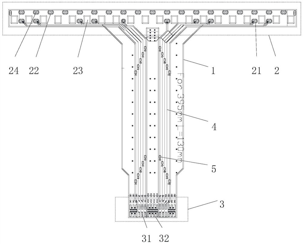
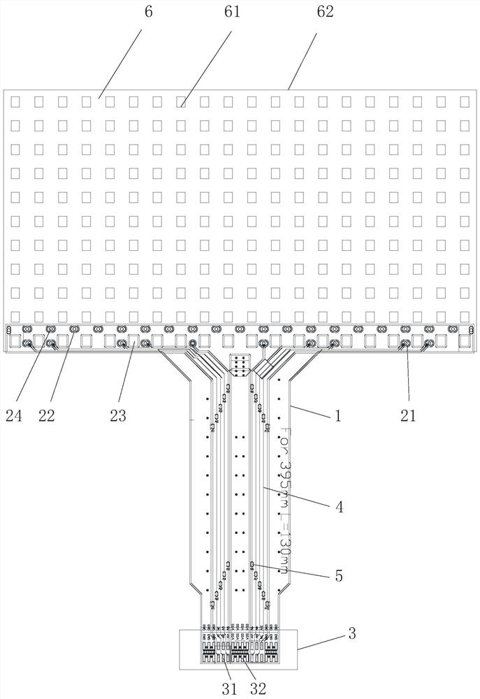
However, the connectors in the prior art have the problem of reducing the effective display area or display effect of the display screen when they are used; specifically, there are power supply lines and signal lines in the display screen, and in order to avoid signal loops and power supply Interference is caused by loop crossing, and for the sake of simplicity of wiring (the display can only be wired on one side), so the power terminals and signal terminals on the display need to be divided into two rows. Further, when the connector and the display After the screen is connected, the power supply pad on the FPC is located above the light-emitting unit (lamp bead or pixel unit) closest to the display body 6, while the signal terminal pad is close to the edge of the display glass circuit, closest to the light-emitting unit. Unit (lamp bead or pixel unit), at the same time, because the power terminal and signal terminal on the display screen are divided into two rows, so the FPC circuit board will be located on the power terminal and signal terminal on the display screen. The light-emitting units (display pixels) between them cause occlusion and form a light-emitting blind area, which reduces the effective display area of ​​the display screen or affects the display effect of the display screen.

Method used


Image

  • Connector and display screen
  • Connector and display screen
  • Connector and display screen

Examples


Embodiment Construction

[0028] The technical scheme of the present invention will be further described in detail below in conjunction with the accompanying drawings and specific embodiments, so that those skilled in the art can better understand the present invention and implement it, but the examples given are not as limitations of the present invention. In this embodiment, it should be understood that the terms "vertical", "transverse", "upper", "lower", "front", "rear", "left", "right", "vertical", "horizontal" ", "top", "bottom", "inner", "outer" and other indicated orientations or positional relationships are based on the orientations or positional relationships shown in the drawings, and are only for the convenience of describing the present invention, rather than indicating or implying the It should not be construed as limiting the invention that a device or element must have a specific orientation, be constructed and operate in a specific orientation.

[0029] It should be noted that when an ...


PUM


Abstract

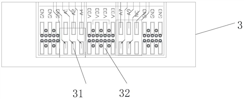
The invention provides a connector and a display screen, the connector comprises a substrate, and a first connecting area and a second connecting area which are respectively arranged on the substrate, the first connecting area is internally provided with a plurality of bonding pads and a plurality of through holes, the bonding pads are arranged around the through holes, the second connecting area is internally provided with a plurality of conductive contact pieces, the plurality of bonding pads and the plurality of conductive contact pieces are electrically connected through a conductive circuit arranged on the substrate, the connector also comprises a display screen substrate, and a mounting area and a non-mounting area which are arranged on the display screen substrate, the mounting area and the non-mounting area are both provided with light-emitting display units, an electric connector is fixed to the mounting area and partially shields the mounting area, the upper light-emitting display unit of the mounting area emits light outwards through the multiple through holes, and the multiple light-emitting display units of the non-mounting area are electrically connected with the light-emitting display unit of the mounting area through a conductive circuit arranged on the display screen substrate. The connector and the display screen have the advantages of being reasonable in structure and capable of improving the effective display area of the display screen.

Description

technical field [0001] The invention belongs to the technical field of display equipment, and in particular relates to a connector and a display screen. Background technique [0002] The transparent display screen has the effect of not blocking sunlight and seeing through, and is often used in glass curtain wall buildings, airports, hotels, stages, shop windows and other occasions. For example, office buildings, exhibition centers, airports, hotels, stages, etc. are all large-scale buildings and commercial spaces in commercial complexes. It is ideal to retain the visual depth of the space, and at the same time make cool multimedia effects Showing a more visual layering and impacting the application scenarios of large shopping malls and chain stores, the transparent display screen perfectly combines the beauty of modern art with the shape of metal, showing the advantage of high transparency, that is, the transparent display screen will not be damaged after installation. It a...

Claims


Application Information

Patent Timeline
Patent Type & Authority Applications(China)
IPC IPC(8): H05K1/11G09F9/30
CPCH05K1/116H05K1/118G09F9/30
Inventor 李天奇
Owner GUANGZHOU QIHONG ELECTRONICS TECH
Learn More