
Sound level meter calibrating device rotary table

A technology for verification devices and sound level meters, which is applied to measuring devices, measuring ultrasonic/sonic/infrasonic waves, instruments, etc., can solve the problems of low verification efficiency, high cut-off frequency, and short sound-absorbing space of the anechoic box, so as to improve the verification Work efficiency, shorten the test time, reduce the effect of work intensity

Pending Publication Date: 2022-01-21
陕西省计量科学研究院
View PDF0 Cites 0 Cited by
  • Summary
  • Abstract
  • Description
  • Claims
  • Application Information

AI Technical Summary

Problems solved by technology

The domestic acoustic equipment manufacturers launched the anechoic box in time, which improved the verification and calibration efficiency of the noise measurement equipment to a certain extent, but the sound absorption space of the anechoic box is short, the space is limited, and the cut-off frequency is high, so it is difficult to meet the requirements of JJF1147-2006 The requirements for the free sound field space range and the background noise in the "Calibration Specifications for Acoustic Characteristics of Anechoic and Semi-Anechoic Rooms" Only one sound level meter can be placed in the anechoic chamber. Therefore, the inspector needs to frequently enter and exit the anechoic chamber for replacement operations, which is time-consuming and laborious, and the verification efficiency is very low.

Method used


Image

  • Sound level meter calibrating device rotary table
  • Sound level meter calibrating device rotary table
  • Sound level meter calibrating device rotary table

Examples


Embodiment 1

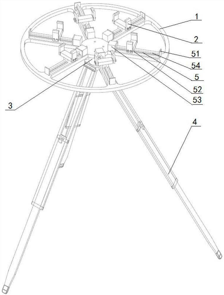
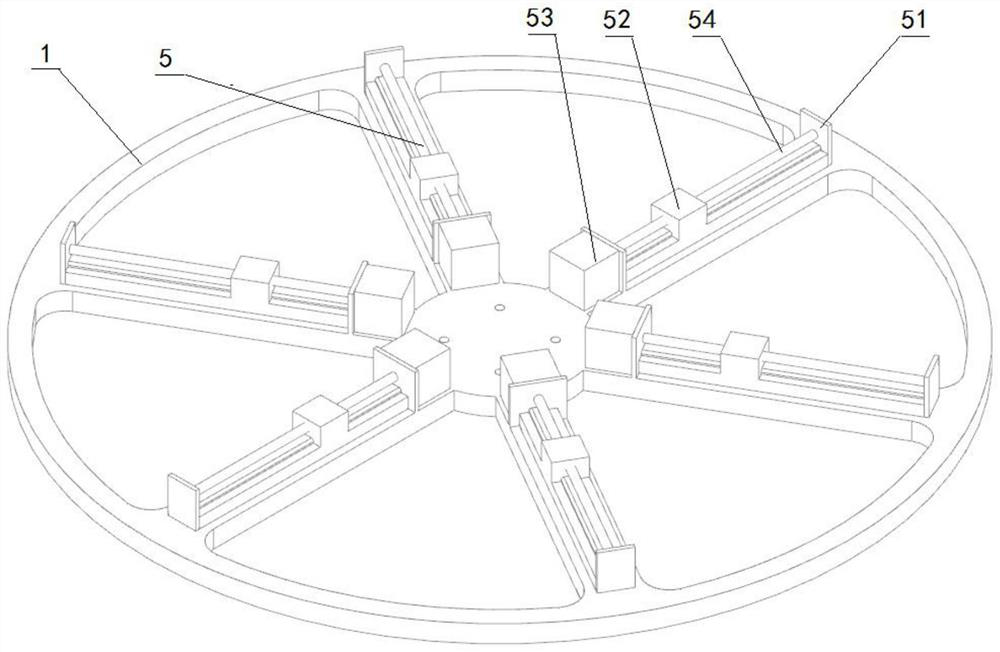
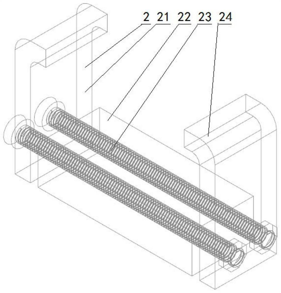
[0039] A sound level meter verification device turntable, such as figure 1 As shown, its structure specifically includes a support device 4 for providing overall support, and a drive assembly 3 for providing power is provided on the upper side of the support device 4. The output of the drive assembly 3 is connected to the turntable 1, and the turntable 1 is arranged on On the upper side of the drive assembly 3, the drive assembly 3 is used to drive the turntable 1 to achieve circumferential angle adjustment. There are multiple fixtures 2 evenly distributed on the turntable 1. The fixtures 2 are used to respectively clamp the standard microphone and multiple tested instruments. 2 can be adjusted along the radial direction of the turntable 1. The turntable 1 is also provided with a detection device for collecting the rotation angle of the turntable 1 . There is a controller on the drive assembly 3 , and the controller is electrically connected to the detection device and the dri...


PUM


Abstract

The invention belongs to the technical field of acoustic measurement, and relates to a sound level meter calibrating device rotary table. The rotary table comprises a supporting device; a driving assembly, arranged on the upper side of the supporting device; a rotary table, arranged on the upper side of the driving assembly and connected with an output piece of the driving assembly, and the driving assembly being used for driving the rotary table to achieve circumferential angle adjustment; a plurality of clamps used for respectively clamping a standard microphone and a plurality of detected instruments and uniformly arranged on the rotary table, and the positions of the clamps being adjustable along the radial direction of the rotary table; a detection device, arranged on the rotary table and used for collecting the rotation angle of the rotary table; a silencing material layer, wrapping the supporting device, the driving assembly, the rotary table and the clamps and used for absorbing echoes and eliminating damage of the support structure to a free sound field; and a controller arranged on the support and electrically connected with the detection device and the driving assembly. According to the invention, a plurality of sound level meters can be calibrated at the same time without destroying a free sound field, the calibration efficiency is improved, and the labor intensity of a calibrator is reduced.

Description

technical field [0001] The invention belongs to the technical field of acoustic measurement, and in particular relates to a turntable of a sound level meter verification device. Background technique [0002] Acoustic measurement in my country started relatively late. At the same time, due to the lack of attention to the prevention and control of noise pollution in the early stage, the use of noise measuring instruments was less. Although some developments have been made in acoustic measurement instruments, the overall level is relatively backward. [0003] In recent years, with the country's emphasis on the prevention and control of noise pollution, noise measuring instruments have been widely used, so the number of sound level meters submitted for inspection has increased significantly. How to ensure the quality of verification and complete the verification work efficiently has become the top priority. The domestic acoustic equipment manufacturers launched the anechoic box...

Claims


Application Information

Patent Timeline
Patent Type & Authority Applications(China)
IPC IPC(8): G01H17/00
CPCG01H17/00
Inventor 李勍白洁郑慧慧付磊兰鹏赵迪吴勇高蒙臧鹏毛斌
Owner 陕西省计量科学研究院
Learn More