A broach mechanism for tool grinder spindle

A tool grinding machine and spindle technology, applied in the direction of manufacturing tools, grinding machine parts, other manufacturing equipment/tools, etc., can solve the problems of lower production efficiency, low safety, limited applicable tools, etc., and achieve easy installation and disassembly , good stopping effect and high production efficiency

Active Publication Date: 2022-08-05
江苏星晨高速电机有限公司
View PDF8 Cites 0 Cited by
  • Summary
  • Abstract
  • Description
  • Claims
  • Application Information

AI Technical Summary

Problems solved by technology

[0002] In the prior art, the broach mechanism mostly uses disc springs or coil springs to provide the broaching force. The broaching force and broaching stroke provided by this structure are limited, and it is inconvenient to adjust. When using different tools, it is difficult To meet various requirements, either set a piston to change the stroke, and change the broach force and stroke by changing the pressure of the piston chamber on both sides of the piston. It is easy to make mistakes during operation, and the applicable tools are limited. When air leakage and other phenomena occur , without a backup solution, the broach mechanism cannot work, reducing production efficiency and low safety

Method used


Image

  • A broach mechanism for tool grinder spindle

Examples


Embodiment 1

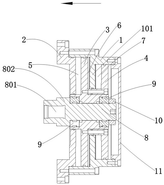
[0028]A broach mechanism for a tool grinder spindle, comprising a cylinder body 1, a cylinder body support sleeve 2 fastened to the cylinder body 1, a first piston 3 arranged inside the cylinder body 1, and a second piston 3 arranged inside the cylinder body 1. Piston 4, mandrel 8, the second piston 4 is sleeved on the first piston 3, and is tightly connected with the first piston 3, and the first piston 3 forms a first non-communicating first piston 3 inside the cylinder 1 Piston chamber 5 and second piston chamber 6, the second piston 4 forms a third piston chamber 7 inside the cylinder 1, the third piston chamber 7 and the first piston chamber 5 are not communicated with each other, the mandrel 8 Coaxially penetrates in the first piston 3, and the mandrel 8 can move axially with the first piston 3, and the mandrel 8 is rotatably connected with the first piston 3; the cylinder support sleeve 2 is installed on the headstock On the body, one end of the mandrel 8 is provided wi...

Embodiment 2

[0033] A broach mechanism for a tool grinder spindle, comprising a cylinder body 1, a cylinder body support sleeve 2 fastened to the cylinder body 1, a first piston 3 arranged inside the cylinder body 1, and a second piston 3 arranged inside the cylinder body 1. Piston 4, mandrel 8, the second piston 4 is sleeved on the first piston 3, and is tightly connected with the first piston 3, and the first piston 3 forms a first non-communicating first piston 3 inside the cylinder 1 The piston chamber 5 and the second piston chamber 6, the second piston 4 forms a third piston chamber 7 inside the cylinder 1, the third piston chamber 7 and the first piston chamber 5 communicate with each other, and the mandrel 8 is the same as the The shaft is penetrated in the first piston 3, and the mandrel 8 can move axially with the first piston 3, and the mandrel 8 is rotatably connected with the first piston 3; the cylinder support sleeve 2 is installed on the main shaft case On the top, one end ...


PUM


Abstract

A broaching mechanism for a tool grinder spindle, comprising a cylinder body (1), a cylinder body support sleeve (2) fastened to the cylinder body (1), and a first piston (3) arranged inside the cylinder body (1) , a second piston (4) and a mandrel (8) arranged inside the cylinder (1), the second piston (4) is sleeved on the first piston (3), and is connected with the first piston (3) Tightly connected, the first piston (3) forms a first piston chamber (5) and a second piston chamber (6) that are not connected to each other inside the cylinder (1), and the second piston is in the cylinder (1) ) inside a third piston cavity (7), the mandrel (8) is coaxially penetrated in the first piston (3), and the mandrel (8) can follow the axial direction of the first piston (3) Movement, the mandrel (8) is connected in rotation with the first piston (3). The invention can provide different strokes for different cutters, has a simple structure, and is easy to install and disassemble.

Description

technical field [0001] The invention relates to the field of tool grinders, in particular to a broach mechanism for a tool grinder spindle. Background technique [0002] In the prior art, the broaching mechanism mostly uses a disc spring or a coil spring to provide the broaching force. The broaching force and broaching stroke provided by this structure are limited, which is inconvenient to adjust. When using different knives, it is difficult to To meet various requirements, either set a piston to change the stroke, and change the broaching force and stroke by changing the pressure of the piston cavity on both sides of the piston. It is prone to errors during operation, and the applicable tools are limited. When air leakage occurs, etc. , Without a backup solution, the broach mechanism cannot work, reducing production efficiency and low safety. SUMMARY OF THE INVENTION [0003] The purpose of the present invention is to provide a broaching mechanism for a tool grinder spin...

Claims


Application Information

Patent Timeline
Patent Type & Authority Patents(China)
IPC IPC(8): B24B3/00B24B41/04B24B55/00
CPCB24B3/00B24B41/04B24B55/00
Inventor 刘钊左宏伟
Owner 江苏星晨高速电机有限公司
Why Eureka
Try Eureka