BIM (Building Information Model) examination method and device, equipment and storage medium
A technology of models and cuboids, applied in 3D modeling, instruments, projection reproduction, etc., can solve the problems of high computer resource usage and slow calculation speed, reduce resource consumption, improve projection effect, and solve excessive computer resource usage Effect
Active Publication Date: 2022-01-28
深圳市毕美科技有限公司
14 Cites 2 Cited by
AI-Extracted Technical Summary
Problems solved by technology
[0004] The main purpose of the present invention is to solve the technical problem that the co...
Method used
[0109] In the embodiment of the present invention, by dismantling and analyzing the BIM model, based on the projection on the two-dimensional surface of the same coordinate system, the spatial collision calculation is converted into Boolean calculation to reduce the resources occupied by the entire operation. Moreover, for a better projection effect, using the smallest circumscribed simulation rule object replacement can also reduce the consumption of computing resources, which not only meets the processing requirements during the review process but also does not cause excessive computer resource consumption, and solves the BIM model problem. A technical issue where the computer under review takes up too many resources, resulting in slow calculations.
[0121] In the embodiment of the present invention, by dismantling and analyzing the BIM model, based on the projection on the two-dimensional surface of the same coordinate system, the spatial collision calculation is converted into Boolean calculation, reducing the resources occupied by the entire operation. Moreover, for a better projection effect, using the smallest circumsc...
Abstract
The invention relates to the field of model examination, and discloses a BIM (Building Information Model) examination method and device, equipment and a storage medium. The method comprises the steps of: obtaining a component set of a to-be-examined BIM; conducting component collision analysis on all components in the component set according to a preset analysis algorithm to obtain the collision state of each component in the component set, the collision states comprising an overlapping state; judging whether there is an overlapping state in the collision states of the components in the component set or not; if there is an overlapping state, determining that the to-be-examined BIM is an unqualified BIM; and if there is no overlapping state, determining that the to-be-examined BIM is a qualified BIM.
Application Domain
Geometric CADReconstruction from projection +3
Technology Topic
Collision analysisSystems engineering +3
Image
Examples
- Experimental program(1)
Example Embodiment
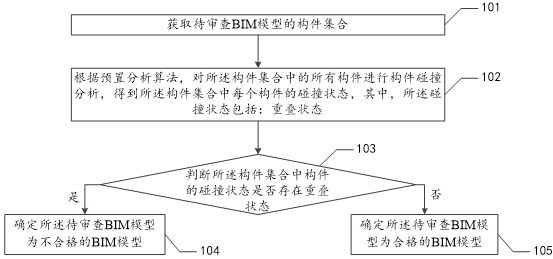
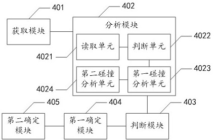
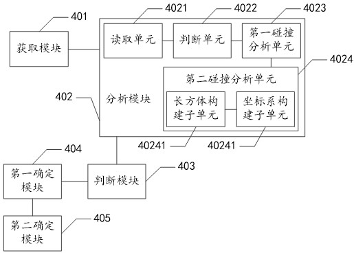
[0059] Embodiments of the present invention provide a BIM model review method, apparatus, device, and storage medium.
[0060] The terms "first", "second", "third", "fourth", etc. (if present) in the description and claims of the present invention and the above-mentioned drawings are used to distinguish similar objects and are not necessarily used to describe a specific order or sequence. It is to be understood that data so used may be interchanged under appropriate circumstances so that the embodiments described herein can be practiced in sequences other than those illustrated or described herein. Furthermore, the terms "comprising" or "having" and any variations thereof are intended to cover non-exclusive inclusion, for example, a process, method, system, product or device comprising a series of steps or units is not necessarily limited to those expressly listed steps or units, but may include other steps or units not expressly listed or inherent to these processes, methods, products or devices.
[0061] For ease of understanding, the following describes the specific process of the embodiment of the present invention, please refer to figure 1 , an embodiment of the BIM model review method in the embodiment of the present invention includes:
[0062] 101. Obtain the component collection of the BIM model to be reviewed;
[0063] In this embodiment, the components in the BIM model include instance attribute parameters and type attribute parameters. The amount of data information is complex and irregular. In order to improve the efficiency of component search, we decompose the content of component storage into two parts: element header and element body. We store frequently searched and key attribute information in the element header, such as: the ID of the component, the name of the component, the category to which the component belongs, the category ID to which the component belongs, the type to which the component belongs, the type ID to which the component belongs, etc. There is very little information; most of the detailed information is stored in the element body, including infrequently searched information, non-critical information, and information with a large amount of data, such as component attribute information, component collection information, etc. When we try to obtain the information of a component, if the component information to be obtained is already contained in the element header, the content of the element body will not be parsed, which saves memory usage and improves the access speed. Only when the acquired component information does not exist in the element header, will the content of the element body be loaded into memory for parsing. Based on a large number of review rules, the data of the component is re-parsed, and the data information that needs to be filtered frequently is stored in the element header, and the general data is stored in the element body. When filtering search components, simply retrieve the data information of the element header. Greatly improve the efficiency of filter components. like figure 2 As shown, it is the organization of the data in the original component. like image 3 As shown, for the information organization method in the optimized component: assign attributes to the corresponding element header and element body respectively. When we search and filter components based on a certain information, the original filtering method, the number of searches for each component is the order of m*n (m is the number of components, n is the number of attributes, and the number level of n is 100 levels) , after we re-parse the attributes of the component, the filtered information is stored in the element header, and fast filtering can be used, and the number of searches for each component can be optimized to the order of m. When we search and filter the information stored in the element body, it is still inefficient if we directly filter the information in the element body. We provide a feasible way to achieve the improvement of review efficiency through the combination of multiple rapid filtering.
[0064] Therefore, when filtering components, we can filter based on the entire document model (slower), or add a layer of fast filtering, filter elements based on a certain view in the document (faster), or even add a layer of fast filtering. , based on a horizontal layer or based on a bounding set (faster), continuous constraints, and fast filtering is achieved through the combination of fast filtering intersections.
[0065] 102. Perform a component collision analysis on all components in the component set according to a preset analysis algorithm, to obtain a collision state of each component in the component set, wherein the collision state includes: an overlapping state;
[0066] In this embodiment, there are many components in the component set, and it is necessary to analyze whether the components collide with each other. The collision state here has an overlapping state, which means that the two components violate the actual physical rules. It is practically impossible in the industry.
[0067] Further, step 102 also includes the following steps:
[0068] 1021. Read the components in the component set in turn, and determine the read component as the target component;
[0069] 1022. Determine whether the target component is a rotating body, wherein the target component includes: a quadrangular prism;
[0070] 1023, if the target component is a rotating body, then read the coordinates of the eight vertices of the target component, calculate the center and radius of the circumscribed ball corresponding to the coordinates of the eight vertices, and according to the center of the circumscribed ball and radius, perform projection analysis processing on the circumscribed sphere to obtain the collision state of the target component;
[0071] 1024. If the target component is not a rotating body, perform state analysis processing on the target component to obtain a collision state of the target component.
[0072] In steps 1021-1024, to analyze the component data in the component set, it is necessary to first take a component from the component set, and determine the picked component as the target component, that is, the component to be analyzed.
[0073] First judge the target component. When the target component is a rotating body, we use the bounding sphere mode for the model that will rotate. In contrast to the hexahedron of the bounding box, the bounding sphere encloses the entire geometry with a sphere. The bounding sphere does not require any updates when the component rotates. First, calculate the 8 vertices of the component enclosing set on the x, y, and z coordinates, determine the center of the surrounding sphere according to the 8 vertices, and then determine the radius r by the distance between the center of the sphere and the three maximum coordinate points. When we calculate the collision detection of the component model that conforms to the bounding sphere, we mainly compare the radius between the two spheres and the distance from the center of the sphere. We can also use the bounding sphere as the projection basis, and project it into each two-dimensional surface to compare whether overlapping.
[0074] When the target component is not a rotating body, it can be judged by conventional analysis.
[0075] Further, the collision state further includes a non-overlapping state, and step 1023 may also perform the following steps:
[0076] 10231. Build a universal coordinate system XYZ, and project all the components in the component set except the target component on the XY plane, YZ plane, and XZ plane in the general coordinate system XYZ in turn, and obtain the three-sided projection data of N non-target components set, N is a positive integer;
[0077] 10232. Project the circumscribed sphere on the XY plane, the YZ plane, and the XZ plane in the universal coordinate system XYZ to obtain a circumscribed sphere projection data set;
[0078] 10233. Determine whether the circumscribed sphere projection data set is overlapped with respect to all the three-plane projection data sets on the XY plane, the YZ plane, and the XZ plane;
[0079] 10234. If both exist, determine that the target component corresponding to the circumscribed ball is in an overlapping state;
[0080] 10235. If non-uniformity exists, determine that the target component corresponding to the circumscribed ball is in a non-overlapping state.
[0081] In steps 10231-10234, the general coordinate system XYZ is the XY plane, YZ plane, and XZ plane in the general coordinate system XYZ that can use the horizontal plane as the basis of the XY plane, and project all the components in the component set except the target component in sequence in the general coordinate system XYZ. Then, N three-sided projection data sets are obtained, and the three-sided projection data set has one projection data on each of the XY plane, the YZ plane, and the XZ plane.
[0082] The circumscribed sphere is projected on the XY plane, the YZ plane, and the XZ plane in the general coordinate system XYZ to obtain the circumscribed sphere projection data set. A projection data.
[0083] During the judgment process, compare the XY plane, YZ plane with the projection of the circumscribed sphere in the XY plane, the YZ plane and the XZ plane and the projection of the XY plane, the YZ plane and the XZ plane in the general coordinate system XYZ of the selected component. The coincidence of the projections on the surface and the XZ surface.
[0084] Further, at 10233 the following steps may be performed:
[0085] 102331. Determine whether the circumscribed sphere projection data set overlaps on the XY plane relative to the three-plane projection data set, and determine whether the circumscribed sphere projection data set is on the YZ plane relative to the three-plane projection data set. If there is overlap, it is determined whether the circumscribed sphere projection data set has overlap on the XZ plane with respect to the three-plane projection data set.
[0086] In step 102331, the XY plane, the YZ plane, and the XZ plane are all compared separately. Different threads can be used to perform the judgment processing at the same time. It is not necessary to read one XY plane to judge and then compare and judge the YZ plane.
[0087] Further, in step 1024, the following steps may be performed:
[0088] 10241. Calculate the minimum inclusive cuboid of the target component to obtain the target cuboid;
[0089] 10242. Calculate the minimum accommodating cuboid corresponding to all the components of the non-target component in the component set, to obtain a comparison cuboid set;
[0090] 10243. Based on Boolean calculation, determine whether the target cuboid overlaps with the comparison cuboids in the comparison cuboids set;
[0091] 10244. If both exist, set the target component corresponding to the determined target cuboid to an overlapping state;
[0092] 10245. If not all exist, set the target component corresponding to the determined target cuboid as a non-overlapping state.
[0093]In the 10241-10245 embodiment, if the bounding boxes of the two directions do not collide, then it should be possible to find the plane where a face on a box is located, and the three-dimensional space can be divided into two parts, and the bounding boxes of the two directions are on both sides. ; If no such surface exists, then an edge must be found on each of the two bounding boxes, and the planes where these two edges are located can divide the bounding boxes of the two directions on both sides. When this plane is found, the coordinate axis perpendicular to this plane can be found. When we project the direction bounding box on the coordinate axis, the projection is separated. When we are checking the collision, since the bounding box in each direction has 6 surfaces, and every two surfaces are parallel, we only need to project the 3 surfaces of the bounding box in each direction on the XY, XZ, YZ coordinates respectively. plane, and each projection overlaps, then it is judged as a collision. For models that are tilted at large angles relative to the horizontal or vertical plane, we use directional bounding boxes. Different from the way that the bounding box generates 2 particles based on the horizontal and vertical directions, the particles generated by the direction bounding box are still based on the vertical direction, but the horizontal direction is changed to the direction of the longest axis of the component to determine the particles. When we calculate the collision detection that conforms to the bounding box of the direction, we only need to calculate whether the projections of the geometry on each coordinate plane overlap. If so, the component is collided, otherwise there is no collision. Computational projection is the transformation of three-dimensional into two-dimensional calculations.
[0094] Further, in step 10241, the following steps can be performed:
[0095] 102411. Build a universal coordinate system XYZ, and read the X maximum value, X minimum value, Y maximum value, Y minimum value, Z maximum value, and Z minimum value of the target component under the construction of the universal coordinate system XYZ;
[0096] 102412. According to the X maximum value, the X minimum value, the Y maximum value, the Y minimum value, the Z maximum value, and the Z minimum value, construct a surface parallel to the general coordinate system XYZ The cuboid is determined as the target cuboid.
[0097] In steps 102411-102412, for models with large volumes and simple characteristics, we use bounding boxes to approximately replace complex models. The bounding box of the component contains 2 mass points (xmin, ymin, zmin), (xmax, ymax, zmax), and any point on the surface of the component satisfies the following conditions: {xmin
[0098] Further, in step 1024, the following steps may be performed:
[0099] 10246, using any surface of the target member as the XY plane to construct a three-dimensional surface coordinate system, and projecting the target member on the XY plane, YZ plane, and XZ plane of the surface three-dimensional coordinate system to obtain the target three-sided projection data;
[0100] 10247. Select the analysis component of the non-target component in the component set, and project the analysis component on the XY plane, the YZ plane, and the XZ plane of the three-dimensional coordinate system of the surface to obtain analysis three-plane projection data;
[0101] 10248. Determine whether the target three-plane projection data is overlapped with respect to the analysis three-plane projection data on the XY plane, the YZ plane, and the XZ plane;
[0102] 10249. If both exist, determine that the target component is in an overlapping state;
[0103] 1024A1. If non-uniformity exists, determine that the target components are in a non-overlapping state.
[0104] In steps 10246-1024A1, if the bounding boxes in the two directions do not collide, then it should be possible to find the plane where a face on a box is located, and the three-dimensional space can be divided into two parts, and the bounding boxes in the two directions are on both sides; If such a surface is not found, then an edge must be found on each of the two bounding boxes, and the planes where these two edges are located can divide the two bounding boxes on both sides. When this plane is found, the coordinate axis perpendicular to this plane can be found. When we project the direction bounding box on the coordinate axis, the projection is separated.
[0105] 103. Determine whether the collision states of the components in the component set have overlapping states;
[0106] 104. If there is an overlapping state, determine that the BIM model to be reviewed is an unqualified BIM model;
[0107] 105. If there is no overlapping state, determine that the BIM model to be reviewed is a qualified BIM model.
[0108] In steps 103-105, if the collision state is determined to have an overlapping state, it means that the content of the BIM model cannot be realized in the BIM model in the presence of a physical reality state. However, the collision state has no overlapping state, and the data of the BIM model can be realized in the physical reality state, so it is determined that the BIM model to be reviewed is a qualified BIM model.
[0109] In the embodiment of the present invention, the BIM model is disassembled and analyzed, and the spatial collision calculation is converted into a Boolean calculation based on the projection on the two-dimensional surface of the same coordinate system, thereby reducing the resources occupied by the entire operation. Moreover, for a better projection effect, using the smallest circumscribed simulation rule object replacement can also reduce the consumption of computing resources, which not only meets the processing requirements during the review process, but also does not generate excessive computer resource consumption, which solves the problem of the BIM model. The computer under review is using too many resources, causing technical issues with slow computing.
[0110] The BIM model review method in the embodiment of the present invention is described above, and the BIM model review device in the embodiment of the present invention is described below, please refer to Figure 4 , an embodiment of the BIM model review device in the embodiment of the present invention includes:
[0111] an acquisition module 401, configured to acquire a component set of the BIM model to be reviewed;
[0112] An analysis module 402, configured to perform a component collision analysis on all components in the component set according to a preset analysis algorithm, to obtain a collision state of each component in the component set, wherein the collision state includes: an overlapping state;
[0113] The judgment module 403 is used for judging whether the collision state of the components in the component set has an overlapping state;
[0114] A first determining module 404, configured to determine that the BIM model to be reviewed is an unqualified BIM model if there is an overlapping state;
[0115] The second determining module 405 is configured to determine that the BIM model to be reviewed is a qualified BIM model if there is no overlapping state;
[0116] Wherein, the analysis module 402 includes:
[0117] a reading unit 4021, configured to sequentially read the components in the component set, and determine the read component as the target component;
[0118] A determination unit 4022, configured to determine whether the target member is a rotating body, wherein the target member includes: a quadrangular prism;
[0119] The first collision analysis unit 4023 is configured to read the coordinates of the eight vertices of the target member if the target member is a rotating body, calculate the center and radius of the circumscribed sphere corresponding to the coordinates of the eight vertices, and according to the The center and radius of the circumscribed sphere, and the projection analysis processing is performed on the circumscribed sphere to obtain the collision state of the target component;
[0120] The second collision analysis unit 4024 is configured to, if the target member is not a rotating body, perform state analysis processing on the target member to obtain the collision state of the target member.
[0121] In the embodiment of the present invention, the BIM model is disassembled and analyzed, and the spatial collision calculation is converted into a Boolean calculation based on the projection on the two-dimensional surface of the same coordinate system, thereby reducing the resources occupied by the entire operation. Moreover, for a better projection effect, using the smallest circumscribed simulation rule object replacement can also reduce the consumption of computing resources, which not only meets the processing requirements during the review process, but also does not generate excessive computer resource consumption, which solves the problem of the BIM model. The computer under review is using too many resources, causing technical issues with slow computing.
[0122] see Figure 5 , another embodiment of the BIM model review device in the embodiment of the present invention includes:
[0123] an acquisition module 401, configured to acquire a component set of the BIM model to be reviewed;
[0124] An analysis module 402, configured to perform a component collision analysis on all components in the component set according to a preset analysis algorithm, to obtain a collision state of each component in the component set, wherein the collision state includes: an overlapping state;
[0125] The judgment module 403 is used for judging whether the collision state of the components in the component set has an overlapping state;
[0126] A first determining module 404, configured to determine that the BIM model to be reviewed is an unqualified BIM model if there is an overlapping state;
[0127] The second determining module 405 is configured to determine that the BIM model to be reviewed is a qualified BIM model if there is no overlapping state.
[0128] Wherein, the analysis module 402 includes:
[0129] a reading unit 4021, configured to sequentially read the components in the component set, and determine the read component as the target component;
[0130] The judgment unit 4022 is used to judge whether the target member is a rotating body, wherein the target member includes: a quadrangular prism;
[0131] The first collision analysis unit 4023 is configured to read the coordinates of the eight vertices of the target member if the target member is a rotating body, calculate the center and radius of the circumscribed sphere corresponding to the coordinates of the eight vertices, and according to the The center and radius of the circumscribed sphere, and projection analysis processing is performed on the circumscribed sphere to obtain the collision state of the target component;
[0132] The second collision analysis unit 4024 is configured to, if the target member is not a rotating body, perform state analysis processing on the target member to obtain the collision state of the target member.
[0133] Wherein, the first collision analysis unit 4023 is specifically used for:
[0134] Constructing a general coordinate system XYZ, projecting all the components in the component set except the target component on the XY plane, YZ plane, and XZ plane in the general coordinate system XYZ in turn, to obtain the three-sided projection data set of N non-target components, N is a positive integer;
[0135] Projecting the circumscribed sphere on the XY plane, the YZ plane, and the XZ plane in the general coordinate system XYZ to obtain a circumscribed sphere projection data set;
[0136] Judging whether the circumscribed sphere projection data set has overlaps on the XY plane, the YZ plane, and the XZ plane relative to all the three-plane projection data sets;
[0137] If both exist, determine that the target component corresponding to the circumscribed ball is in an overlapping state;
[0138] If the unevenness exists, it is determined that the target member corresponding to the circumscribed ball is in a non-overlapping state.
[0139] Wherein, the first collision analysis unit 4023 is also specifically used for:
[0140] Determine whether the circumscribed sphere projection data set overlaps on the XY plane relative to the three-plane projection data set, and determine whether the circumscribed sphere projection data set overlaps on the YZ plane relative to the three-plane projection data set In the case of the circumscribing sphere projection data set, it is judged whether there is overlap on the XZ plane with respect to the three-plane projection data set.
[0141] Wherein, the second collision analysis unit 4024 is specifically used for:
[0142] Calculate the minimum inclusive cuboid of the target component to obtain the target cuboid;
[0143] Calculate the minimum inclusive cuboid corresponding to all the components of the non-target component in the component set, and obtain a comparison cuboid set;
[0144] Based on Boolean calculation, determine whether the target cuboid is overlapped with the comparison cuboids in the comparison cuboids set;
[0145] If both exist, the determined target components corresponding to the target cuboid are in an overlapping state;
[0146] If non-uniformity exists, the determined target component corresponding to the target cuboid is in a non-overlapping state.
[0147] Wherein, the second collision analysis unit 4024 includes:
[0148] The coordinate system construction subunit 40241 is used to construct a general coordinate system XYZ, and read the X maximum value, X minimum value, Y maximum value, Y minimum value, and Z maximum value of the target component under the construction general coordinate system XYZ , Z minimum value;
[0149] The cuboid construction subunit 40242 is configured to construct a surface parallel to the surface according to the X maximum value, the X minimum value, the Y maximum value, the Y minimum value, the Z maximum value, and the Z minimum value. The rectangular parallelepiped of the general coordinate system XYZ is determined as the target rectangular parallelepiped.
[0150] Wherein, the second collision analysis unit 4024 is also specifically used for:
[0151] Taking any surface of the target component as an XY plane to construct a surface three-dimensional coordinate system, projecting the target component on the XY plane, YZ plane, and XZ plane of the surface three-dimensional coordinate system to obtain target three-sided projection data;
[0152] Selecting an analysis component of a non-target component in the component set, and projecting the analysis component on the XY plane, the YZ plane, and the XZ plane of the three-dimensional coordinate system of the surface, to obtain analysis three-plane projection data;
[0153] Judging whether the target three-plane projection data is overlapped on the XY plane, the YZ plane, and the XZ plane relative to the analysis three plane projection data;
[0154] If both exist, determine that the target component is in an overlapping state;
[0155] If unevenness exists, it is determined that the target member is in a non-overlapping state.
[0156] In the embodiment of the present invention, the BIM model is disassembled and analyzed, and the spatial collision calculation is converted into a Boolean calculation based on the projection on the two-dimensional surface of the same coordinate system, thereby reducing the resources occupied by the entire operation. Moreover, for a better projection effect, using the smallest circumscribed simulation rule object replacement can also reduce the consumption of computing resources, which not only meets the processing requirements during the review process, but also does not generate excessive computer resource consumption, which solves the problem of the BIM model. The computer under review is using too many resources, causing technical issues with slow computing.
[0157] above Figure 4 and Figure 5 The BIM model review device in the embodiment of the present invention is described in detail from the perspective of modular functional entities, and the BIM model review device in the embodiment of the present invention is described in detail below from the perspective of hardware processing.
[0158] Image 6 This is a schematic structural diagram of a BIM model review device provided by an embodiment of the present invention. The BIM model review device 600 may have relatively large differences due to different configurations or performances, and may include one or more processors (central processing units, CPUs). ) 610 (eg, one or more processors) and memory 620 , one or more storage media 630 (eg, one or more mass storage devices) storing applications 633 or data 632 . Among them, the memory 620 and the storage medium 630 may be short-term storage or persistent storage. The program stored in the storage medium 630 may include one or more modules (not shown in the figure), and each module may include a series of instruction operations on the BIM model review apparatus 600 . Furthermore, the processor 610 may be configured to communicate with the storage medium 630 to execute a series of instruction operations in the storage medium 630 on the BIM model review device 600 .
[0159] The BIM model-based review device 600 may also include one or more power supplies 640, one or more wired or wireless network interfaces 650, one or more input and output interfaces 660, and/or, one or more operating systems 631, such as Windows Serve, Mac OS X, Unix, Linux, FreeBSD and many more. Those skilled in the art can understand that, Image 6 The illustrated structure of the BIM model review equipment does not constitute a limitation to the BIM model-based review equipment, and may include more or less components than those shown, or combine some components, or different component arrangements.
[0160] The present invention also provides a computer-readable storage medium. The computer-readable storage medium may be a non-volatile computer-readable storage medium. The computer-readable storage medium may also be a volatile computer-readable storage medium. The computer-readable storage medium stores instructions that, when executed on a computer, cause the computer to perform the steps of the BIM model review method.
[0161] Those skilled in the art can clearly understand that, for the convenience and brevity of description, the specific working process of the above-described system, device, and unit may refer to the corresponding process in the foregoing method embodiments, which will not be repeated here.
[0162] The integrated unit, if implemented in the form of a software functional unit and sold or used as an independent product, may be stored in a computer-readable storage medium. Based on such understanding, the technical solution of the present invention is essentially or the part that contributes to the prior art, or all or part of the technical solution can be embodied in the form of a software product, and the computer software product is stored in a storage medium , including several instructions for causing a computer device (which may be a personal computer, a server, or a network device, etc.) to execute all or part of the steps of the methods described in the various embodiments of the present invention. The aforementioned storage medium includes: U disk, mobile hard disk, read-only memory (ROM), random access memory (RAM), magnetic disk or optical disk and other media that can store program codes .
[0163] As mentioned above, the above embodiments are only used to illustrate the technical solutions of the present invention, but not to limit them; although the present invention has been described in detail with reference to the foregoing embodiments, those of ordinary skill in the art should understand: The technical solutions described in the embodiments are modified, or some technical features thereof are equivalently replaced; and these modifications or replacements do not make the essence of the corresponding technical solutions depart from the spirit and scope of the technical solutions of the embodiments of the present invention.
PUM


Description & Claims & Application Information
We can also present the details of the Description, Claims and Application information to help users get a comprehensive understanding of the technical details of the patent, such as background art, summary of invention, brief description of drawings, description of embodiments, and other original content. On the other hand, users can also determine the specific scope of protection of the technology through the list of claims; as well as understand the changes in the life cycle of the technology with the presentation of the patent timeline. Login to view more.
Similar technology patents
Method and system for detecting blackmail application under Android platform
Owner:WUHAN ANTIY MOBILE SECURITY
Construction method of intelligent dialogue system
Owner:SHANDONG LANGCHAO YUNTOU INFORMATION TECH CO LTD
Assembly-type physical dart target
ActiveUS20210190462A1good projection effectwork well
Owner:HO MING CHENG
Security market TCP/IP message rapid processing device and method
Owner:南京艾科朗克信息科技有限公司
Projection dustproof device for information technology
InactiveCN111399323APrevent image sharpness from degradingGood projection effect
Owner:WUYI XIANHE ELECTRONICS CO LTD
SDRAM high-capacity image data register based on FPGA
InactiveCN103607521AConsume less resourcesImprove timing performance
Owner:UNIV OF ELECTRONIC SCI & TECH OF CHINA
Classification and recommendation of technical efficacy words
- Consume less resources
- Good projection effect
Method and system for detecting blackmail application under Android platform
Owner:WUHAN ANTIY MOBILE SECURITY
SDRAM high-capacity image data register based on FPGA
InactiveCN103607521AConsume less resourcesImprove timing performance
Owner:UNIV OF ELECTRONIC SCI & TECH OF CHINA
Security market TCP/IP message rapid processing device and method
Owner:南京艾科朗克信息科技有限公司
Construction method of intelligent dialogue system
Owner:SHANDONG LANGCHAO YUNTOU INFORMATION TECH CO LTD
Assembly-type physical dart target
ActiveUS20210190462A1good projection effectwork well
Owner:HO MING CHENG
Projection dustproof device for information technology
InactiveCN111399323APrevent image sharpness from degradingGood projection effect
Owner:WUYI XIANHE ELECTRONICS CO LTD