
Electric carbon factor prediction and evaluation method and device and readable storage medium

An electric carbon factor and factor technology, which is applied in forecasting, electric digital data processing, instruments, etc., can solve the problems of insufficiency of electric carbon factor, inaccurate calculation of electric carbon factor, and inability to meet the requirements of accurate accounting and real-time monitoring of carbon emissions. , to achieve the effect of accurate electric carbon factor and guarantee accuracy

Active Publication Date: 2022-01-28
STATE GRID ZHEJIANG ELECTRIC POWER
View PDF13 Cites 3 Cited by
  • Summary
  • Abstract
  • Description
  • Claims
  • Application Information

AI Technical Summary

Problems solved by technology

With the great optimization of China's power generation structure and the significant increase in the proportion of renewable energy, the electricity carbon factor in 2012 can no longer meet the current needs of formulating a carbon peak and carbon neutral roadmap, nor can it meet the carbon emission requirements of major industrial enterprises. The need for accurate accounting and real-time monitoring
[0003] Due to the different objective geographical conditions of different power grid regions, there will be certain differences in the way of generating electric energy in each power grid region, and the conditions for carbon neutralization through tree planting and other methods are also different. The electric carbon factor prediction method of the prior art , did not fully consider the objective conditions of each grid region and the carbon neutral behavior of the region, resulting in inaccurate calculation of the electricity carbon factor

Method used


Image

  • Electric carbon factor prediction and evaluation method and device and readable storage medium
  • Electric carbon factor prediction and evaluation method and device and readable storage medium
  • Electric carbon factor prediction and evaluation method and device and readable storage medium

Examples


Embodiment Construction

[0062] In order to make the purpose, technical solutions and advantages of the embodiments of the present invention clearer, the technical solutions in the embodiments of the present invention will be clearly and completely described below in conjunction with the drawings in the embodiments of the present invention. Obviously, the described embodiments It is only some embodiments of the present invention, but not all embodiments. Based on the embodiments of the present invention, all other embodiments obtained by persons of ordinary skill in the art without making creative efforts belong to the protection scope of the present invention.

[0063] The terms "first", "second", "third", "fourth", etc. (if any) in the description and claims of the present invention and the above drawings are used to distinguish similar objects and not necessarily Describe a specific order or sequence. It is to be understood that the data so used are interchangeable under appropriate circumstances ...


PUM


Abstract

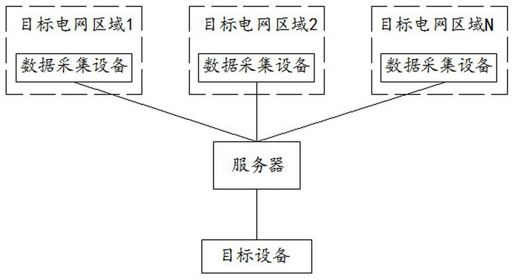
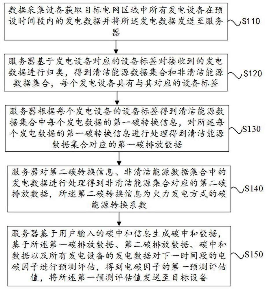
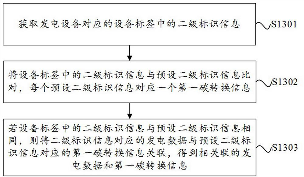
The invention provides an electric carbon factor prediction and evaluation method and device and a readable storage medium. The method comprises the steps of classifying power generation data based on an equipment label corresponding to power generation equipment to obtain a clean energy data set and a non-clean energy data set; obtaining first carbon conversion information of each power generation data in the clean energy data set, and processing the first carbon conversion information of each power generation data to obtain first carbon emission data corresponding to the clean energy data set; processing the second carbon conversion information and power generation data in the non-clean energy data set to obtain second carbon emission data corresponding to the non-clean energy data set; and obtaining a first prediction evaluation value of the electric carbon factor based on the first carbon emission data, the second carbon emission data, the carbon neutralization data and the power generation data. According to the technical scheme provided by the invention, different power generation modes and different carbon neutralization behaviors of different power generation equipment in each power grid region can be fully considered, and more accurate and objective power carbon factors in the power grid region can be obtained.

Description

technical field [0001] The invention relates to the technical field of electric carbon factors, in particular to a method, device and readable storage medium for predicting and evaluating electric carbon factors. Background technique [0002] The electricity carbon factor refers to the carbon emission corresponding to every kilowatt-hour of electricity consumed. Grid electricity carbon factor refers to the carbon emission level per unit of electricity in the area covered by the grid. The higher the proportion of thermal power in the region, the greater the electrical carbon factor; the higher the proportion of renewable energy, the smaller the electrical carbon factor. At present, the carbon factor of regional power grids adopted in my country is calculated based on weighted data such as power generation, fuel consumption for power generation, and average low calorific value of fuel for power generation in 2012. With the great optimization of China's power generation struc...

Claims


Application Information

Patent Timeline
Patent Type & Authority Applications(China)
IPC IPC(8): G06Q10/04G06Q10/06G06Q50/06G06F30/20G06F113/06
CPCG06Q10/04G06Q10/06312G06Q50/06G06F30/20G06F2113/06Y02P90/84Y04S10/50
Inventor 王红凯戴铁潮黄建平王文黄宇腾陈可周升何东饶涵宇张辰赵帅
Owner STATE GRID ZHEJIANG ELECTRIC POWER
Learn More