A penetrating heat dissipation device for the chip of the board under test

A heat sink, penetrating technology, used in semiconductor/solid state device parts, semiconductor devices, electrical components, etc., can solve the complex structure of air duct components and air compression equipment, increase design and processing costs, and cannot meet heat dissipation requirements. and other problems, to achieve the effect of improving maintenance efficiency, improving heat dissipation effect, and reducing the risk of overlapping

Active Publication Date: 2022-07-19
P&R MEASUREMENT INC
View PDF6 Cites 0 Cited by
  • Summary
  • Abstract
  • Description
  • Claims
  • Application Information

AI Technical Summary

Problems solved by technology

[0004] First, the inner cavity of the needle carrier is designed to install an air duct cooling device, the cooling air will always accumulate in the inner cavity of the needle carrier, and the heat cannot be dissipated
[0005] Second, in order to ensure the air volume of the air duct blowing and heat dissipation scheme, it is generally necessary to introduce air compression equipment, and the needle carrier board needs to reserve a large inner cavity for the installation of related air duct components. The inner cavity area is very easy to test the overlap of pinhole positions. Directly affect the needle of the test point, and the ability to be compatible with different chips of the tested product is poor
[0006] Third, the structure of air duct components and air compression equipment is complex, and its installation and design are difficult, which increases design and processing costs
At the same time, disassembly and assembly are complicated, which is not conducive to disassembly and maintenance
[0007] Fourth, for the backside chip with high working power and high heat generation, the air duct blowing heat dissipation method will not meet the heat dissipation requirements, resulting in poor testing and even the risk of burning the board

Method used


Image

  • A penetrating heat dissipation device for the chip of the board under test
  • A penetrating heat dissipation device for the chip of the board under test
  • A penetrating heat dissipation device for the chip of the board under test

Examples


Embodiment Construction

[0037] The present invention will be further described in detail below in conjunction with the accompanying drawings.

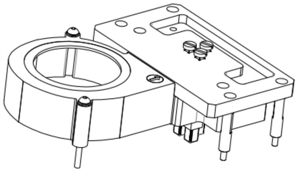
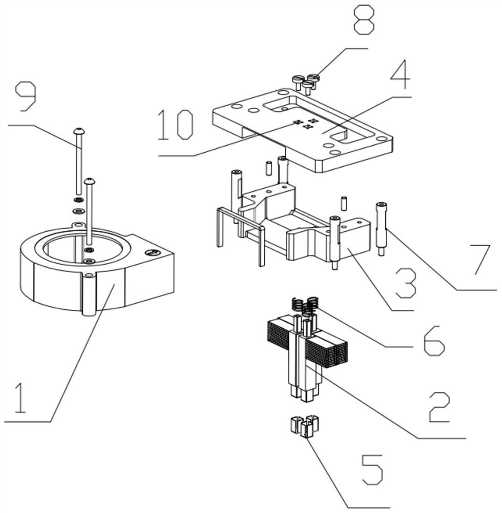
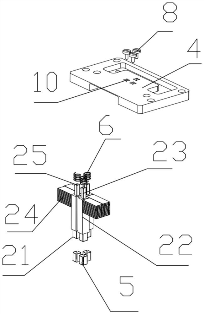
[0038] like Figure 1-3 As shown, the present invention provides a penetrating heat dissipation device for a board card chip under test, comprising: a penetrating heat dissipation module 1-1; the penetrating heat dissipation module 1-1 includes a heat dissipation module The base plate 4, the height screws 8 of the heat dissipation block, the air guide cover 3, the turbo fan 1, the heat dissipation block floating spring 6 and the penetrating heat dissipation block 2; the air guide cover 3 is installed on the bottom surface of the heat dissipation module base plate 4, and the The wind guide cover includes through holes, and the turbo fan 1 is installed on the wind guide cover 3;

[0039] The penetrating heat dissipation block includes a penetrating column 22, the lower end of the penetrating column 22 is provided with a heat dissipation block contact boss 21, ...


PUM


Abstract

The invention relates to a penetrating heat dissipation device for a board card chip under test, comprising: a penetrating heat dissipation module; the penetrating heat dissipation module includes a penetrating heat dissipation block; the penetrating heat dissipation block Including a penetrating column, the lower end of the penetrating column is provided with a heat dissipation block contact boss, the upper end is provided with a heat dissipation block guide column, the inner side of the heat dissipation block guide column is provided with a mounting threaded hole, and the heat dissipation block floating spring is sleeved on the heat dissipation block. the outer side of the block guide column; the heat dissipation block guide column of the penetrating heat dissipation block passes through the through hole of the air guide cover, the heat dissipation module base plate is also provided with a heat dissipation block guide groove, and the heat dissipation block equal-height screws pass through the heat dissipation block. The quick guide groove is screwed with the mounting threaded hole of the guide post of the heat dissipation block, so that the penetrating heat dissipation block is fixed on the base plate of the heat dissipation module. The heat is transferred through the penetrating square column to the heat dissipation fins at the end of the penetrating square column.

Description

technical field [0001] The invention relates to the technical field of heat dissipation devices, in particular to a penetrating heat dissipation device for a chip of a board card under test. Background technique [0002] With the rapid development of electronic product technology and the increasing requirements for process efficiency and yield, the electronic industry has gradually begun to strengthen the development and optimization of product functional testing equipment while improving the process efficiency of electronic products. Among them, the demand for functional testing of electronic product motherboards is the most urgent. In the process of high-performance chip testing, the heat dissipation efficiency of the chip's heat dissipation module is the most critical. [0003] The chip under test is divided into two categories, one is the chip on the front side of the card under test, and the other is the chip on the back side of the card under test. For the heat dissi...

Claims


Application Information

Patent Timeline
Patent Type & Authority Patents(China)
IPC IPC(8): H01L23/367H01L23/40
CPCH01L23/3672H01L23/3677H01L23/4006
Inventor 莫宗杰杨兴华莫荣键黄奕鸿王飞
Owner P&R MEASUREMENT INC
Why Eureka
Try Eureka