High-precision flow control valve for fluid control

A flow control valve, high-precision technology, applied in the direction of fluid flow, lift valve, valve details, etc., can solve problems such as insufficient power, reduced blade lift, and inability to self-regulate and control flow.

Pending Publication Date: 2022-02-01
SHENZHEN ZHENGHUI FLUID CONTROL TECH CO LTD
View PDF0 Cites 0 Cited by
  • Summary
  • Abstract
  • Description
  • Claims
  • Application Information

AI Technical Summary

Problems solved by technology

[0004] Aiming at the deficiencies in the use of the existing throttle valve proposed in the background technology, the present invention provides a high-precision flow control valve for fluid control, which is equipped with a fluid impact fan blade to make it rotate to obtain lift and fluid pressure increase. The lift force of the fan blade increases, and the increase of the lift force of the blade makes the valve core press down to reduce the opening; Move down and pull the pull rope to make the rotating rod drive the rotating blade to rotate to form a gap, so that the fluid with increased turbulence flows through the gap formed to complete the advantage of steady flow, which solves the problem that the throttle valve cannot self-adjust according to the change of fluid pressure in the above background technology Technical problems such as impact damage to subsequent components caused by flow control and unstable flow, insufficient power, etc.

Method used


Image

  • High-precision flow control valve for fluid control
  • High-precision flow control valve for fluid control
  • High-precision flow control valve for fluid control

Examples


Embodiment Construction

[0020] The following will clearly and completely describe the technical solutions in the embodiments of the present invention with reference to the accompanying drawings in the embodiments of the present invention. Obviously, the described embodiments are only some, not all, embodiments of the present invention. Based on the embodiments of the present invention, all other embodiments obtained by persons of ordinary skill in the art without making creative efforts belong to the protection scope of the present invention.

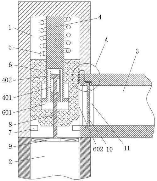
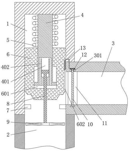
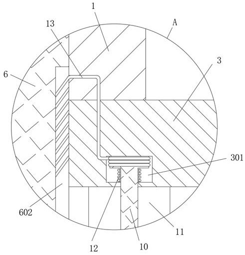
[0021] see Figure 1-Figure 3 , a high-precision flow control valve for fluid control, including a valve body 1, a liquid inlet pipe 2 located at the bottom of the valve body 1, a liquid outlet pipe 3 located at the bottom side of the valve body 1, and the bottom of the inner cavity of the valve body 1 The valve seat 7 is fixedly connected, and the valve seat 7 is located below the liquid outlet pipe 3. The top center of the inner cavity of the valve body 1 is...


PUM


Abstract

The invention relates to the technical field of valves, and discloses a high-precision flow control valve for fluid control, which comprises a valve body, a liquid inlet pipe positioned at the bottom end of the valve body and a liquid outlet pipe positioned on one side of the bottom of the valve body, a valve seat is fixedly connected to the bottom of an inner cavity of the valve body, and a valve rod is fixedly connected to the center of the top end of the inner cavity of the valve body. A center cavity and a transmission channel are formed in the bottom of the valve rod, and a reciprocating rod is movably connected in the center cavity in a sleeved mode. By designing the valve rod, a valve element, fan blades and the reciprocating rod, when a pulsation phenomenon occurs in fluid in a pipeline and the pressure of the fluid in the pipeline is changed, the rotating speed of the fan blades and the front and back water pressure under the impact of water flow are changed, the rising force of the fan blades is changed, and the fan blades drive the reciprocating rod to extrude hydraulic oil in a center cavity; and the elastic force of the spring is matched, so that the valve element completes pressure self-compensation and moves up and down, the throttling section is automatically adjusted, and the output fluid flow is kept constant.

Description

technical field [0001] The invention relates to the technical field of valves, in particular to a high-precision flow control valve for fluid control. Background technique [0002] The throttle valve is a kind of flow control valve, which mainly controls the fluid flow by changing the throttle cross section or throttle length, and is usually used in hydraulic systems, pneumatic transmission systems, etc. [0003] The existing throttle valve, because there is no flow feedback function, makes the opening of the throttle valve still maintain when the fluid pressure in the system increases or decreases or pulsates after the flow passing value is set. This means that when the fluid pressure in the system increases, the flow through the throttle valve increases, and when the fluid pressure in the system decreases, the flow through the throttle valve decreases, and the fluid flow in the system Fluctuation does not always remain the same. Fluid pulsation and impact often occur due ...

Claims


Application Information

Patent Timeline
Patent Type & Authority Applications(China)
IPC IPC(8): F16K17/30F16K17/28F16K27/02F16K1/22F16K1/32F16K31/46F15D1/02
CPCF16K17/30F16K17/28F16K27/02F16K1/221F16K1/223F16K1/32F16K31/465F15D1/025F15D1/02
Inventor 黄思苗张亦建
Owner SHENZHEN ZHENGHUI FLUID CONTROL TECH CO LTD
Why Eureka
Try Eureka