
Volumetric pump

A volumetric pump and volumetric technology, applied in the field of volumetric pumps, can solve problems such as discontinuous flow rate, and achieve the effects of wide range of speed variation, less noise, and low thermal resistance

Pending Publication Date: 2019-06-28
PAGANI GEOTECHNICAL EQUIP SRL
View PDF5 Cites 0 Cited by
  • Summary
  • Abstract
  • Description
  • Claims
  • Application Information

AI Technical Summary

Problems solved by technology

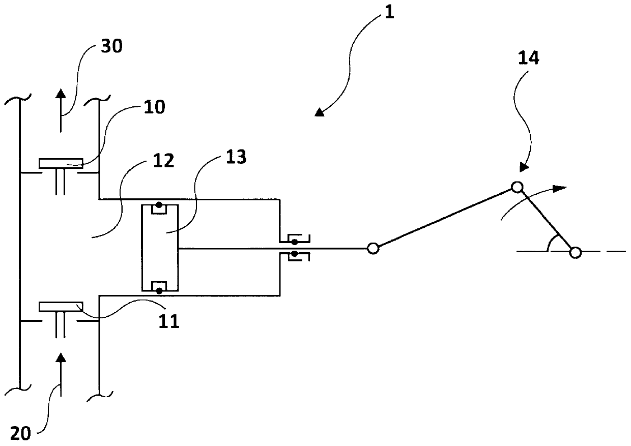
In any case, however, the deceleration-stop-stroke reversal-acceleration sequence of steps induces a discontinuous flow rate, even if to a lesser extent than the aforementioned single-acting link-crank system

Method used


Image

  • Volumetric pump
  • Volumetric pump
  • Volumetric pump

Examples


Embodiment Construction

[0047] Reference attached Figure 5 , according to the invention, the volumetric pump denoted by reference numeral 5 comprises an inlet part 53 and an outlet part 54 in the most basic embodiment.

[0048] Starting from the inlet portion 53 , the pump body is then divided into two branches 61 and 62 . In a first of these branches, for example branch 61 , a first volume 511 of variable geometry is located, which is connected to said inlet part 53 by a first suction valve 611 and through a first suction valve 611 . A delivery valve 612 is connected to the outlet portion 54 .

[0049] In a second branch, such as branch 62 , a second variable geometry volume 521 is located, which is connected to said inlet portion 53 by a second suction valve 621 and connected by a second delivery valve 622 to the outlet section 54 .

[0050] The pump 5 according to the invention also comprises first means 51 for varying the volume of said first volume 511 of variable geometry, and second means ...


PUM


Abstract

The present invention relates to a volumetric pump that comprises an inlet section and an outlet section. The pump also comprises a first volume with variable geometry that is connected through a first suction valve to the inlet section and through a first delivery valve to the outlet section, and a second volume with variable geometry that is connected through a second suction valve to the inletsection and through a second delivery valve to the outlet section. There are also provided first means for varying the volume of said first volume with variable geometry and second means for varying the volume of the second volume with variable geometry, and actuator means of said first means for varying the volume of the first volume with variable geometry and of said second means for varying thevolume of the second volume with variable geometry. Advantageously, the actuator means comprise a servo motor.

Description

technical field [0001] The present invention relates to a positive displacement pump, in particular to a positive displacement pump with improved characteristics in terms of flow rate. More particularly, the present invention relates to a positive displacement pump characterized by being able to provide an almost constant flow rate, or at least with minimized fluctuations. Background technique [0002] Positive displacement pumps are known machines for compressible fluids, the main feature of which is to provide a volume of liquid with variable geometry, which is alternately placed in communication with the suction side during filling and with the delivery side during emptying . In the case of liquids, due to the low compressibility of liquids, the pump will only "move" the fluid from an environment at a lower pressure to an environment at a higher pressure. The average velocity of the fluid inside the pump is usually very low, so that, unlike constant flow machines, the a...

Claims


Application Information

Patent Timeline
IPC IPC(8): F04B1/02F04B11/00F04B17/03F04B49/06F04B49/20
CPCF04B1/02F04B11/0058F04B17/03F04B49/06F04B49/20F04B2205/09F04B11/0041F04B23/06
Inventor E·帕加尼
Owner PAGANI GEOTECHNICAL EQUIP SRL
Learn More