A temperature control valve spool and an automatic temperature control valve

A temperature-controlled valve, automatic technology, applied in valve details, valve devices, multi-way valves, etc., can solve the problems of easy damage to the push rod, unreproducible push rod movement, inconvenient operation, etc., to ensure flow, difficult to pressure. Disturbances of changes and sudden fluctuations, effects of design stability

Active Publication Date: 2020-05-19
GUODIAN ENVIRONMENTAL PROTECTION RES INST CO LTD
View PDF8 Cites 0 Cited by
  • Summary
  • Abstract
  • Description
  • Claims
  • Application Information

AI Technical Summary

Problems solved by technology

The manual temperature control valve controls the ratio of cold and hot fluids by manually adjusting the valve core, and then controls the temperature of the outlet fluid, which has the disadvantage of inconvenient operation
The automatic temperature control valve uses the thermal expansion and contraction of the thermostat controller to push the valve stem to change the valve opening, change the flow ratio of cold and hot fluids, and make the temperature reach the set temperature, but the automatic temperature control valve disclosed in the prior art Control valves basically have various problems such as temperature control delay, push rod movement cannot be reproduced, and push rod is easily damaged.

Method used


Image

  • A temperature control valve spool and an automatic temperature control valve
  • A temperature control valve spool and an automatic temperature control valve
  • A temperature control valve spool and an automatic temperature control valve

Examples


Embodiment Construction

[0025] The present invention will be described in detail below in conjunction with the accompanying drawings.

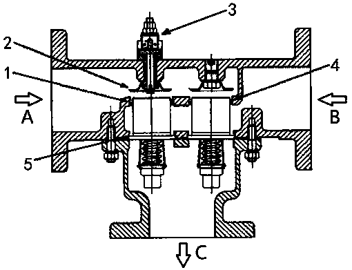
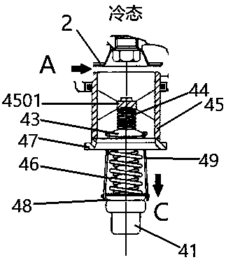
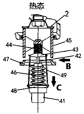
[0026] Such as figure 1 As shown, the temperature control valve automatic temperature control valve of the present invention has three ports of hot end inlet A, cold end inlet B and mixing outlet C, mainly composed of valve housing 1, valve seat 2, adjusting nut 3, valve core 4 Composed of sealing ring 5, etc., one or more identical spools 4 can be configured in parallel to meet the needs of different flow rates (parallel design of spools 4 according to the diameters of A, B, and C ports), so the present invention provides The automatic temperature control valve has wide applicability in a large flow range. In this embodiment, two spools 4 are connected in parallel as an example for structural description. Each spool 4 includes a temperature sensing package 41, a return spring 46, a spool push rod 42, a spool base 47, a spool bushing 43, an overload spring 44, and ...


PUM


Abstract

The invention discloses a temperature control valve element and an automatic temperature control valve adopting the same. The valve element comprises a temperature wrap, a reset spring, a valve element push rod, a valve element base, a valve element bushing, an overload spring and a valve element sliding sleeve; a spring limiting block is fixedly arranged in the valve element sliding sleeve; a temperature wrap is arranged at one end of the valve element push rod; the other end of the valve element push rod freely and slidably penetrates through the valve element base and the spring limiting block in sequence; the valve element bushing is located between the valve element base and the spring limiting block and fixedly connected with the valve element push rod; the reset spring and the overload spring are arranged at the two ends of the valve element push rod correspondingly in a sleeving mode; the two ends of the reset spring abut against the temperature wrap and the valve element basecorrespondingly; the two ends of the overload spring abut against the valve element bushing and the spring limiting block correspondingly; and a fluid channel is formed in the valve element base. According to the temperature control valve element adopted by the invention, through the design of the two springs and the valve element sliding sleeve, sensitive regulation of the temperature change canbe achieved, the valve element is not prone to being interfered by pressure change and sudden fluctuation, and temperature control is more stable.

Description

technical field [0001] The invention relates to the technical field of valves, in particular to a valve core for an automatic temperature control valve and the automatic temperature control valve. Background technique [0002] Temperature control valve, as the name suggests, is a valve that controls the temperature of the fluid, which is divided into manual and automatic. The manual temperature control valve controls the ratio of cold and hot fluids by manually adjusting the valve core, and then controls the temperature of the outlet fluid, which has the disadvantage of inconvenient operation. The automatic temperature control valve uses the thermal expansion and contraction of the thermostat controller to push the valve stem to change the valve opening, change the flow ratio of cold and hot fluids, and make the temperature reach the set temperature, but the automatic temperature control valve disclosed in the prior art Control valves basically have various problems such as...

Claims


Application Information

Patent Timeline
Patent Type & Authority Patents(China)
IPC IPC(8): F16K11/10F16K31/70F16K27/02
CPCF16K11/10F16K27/0263F16K31/002
Inventor 王文飞徐泽鹏黄宣刘志坦郝洪亮王凯朱鸿飞李玉刚曹炼博严志远王婷
Owner GUODIAN ENVIRONMENTAL PROTECTION RES INST CO LTD
Why Eureka
Try Eureka