Eureka AIR delivers breakthrough ideas for toughest innovation challenges, trusted by R&D personnel around the world.

Setting device

a technology of a setting device and a ring, which is applied in the direction of stapling tools, manufacturing tools, nailing tools, etc., can solve the problems of inability to qualitatively determine the type of jam, wear cannot be detected in wearing parts,

Active Publication Date: 2005-01-06
HILTI AG
View PDF10 Cites 23 Cited by
  • Summary
  • Abstract
  • Description
  • Claims
  • Application Information

AI Technical Summary

Benefits of technology

[0007] It is particularly advantageous when the monitoring device comprises a device for pattern recognition which comprises a data processing unit for comparison of measurement data patterns with stored parameter data patterns of known device states. The stored parameter data patterns of known device states are determined in a learning operation prior to the manufacture of the setting device according to the invention. By means of the device for pattern recognition, the data patterns which are supplied by the sensor array or sensor arrays and which comprise a plurality of sensor signal vectors can be correlated with determined operating states or operating situations based on the learned parameter data patterns. Accordingly, the device for pattern recognition can recognize, e.g., a piston which is worn beyond the maximum allowance and can alert the user of the setting device about this state and switch off the setting device.
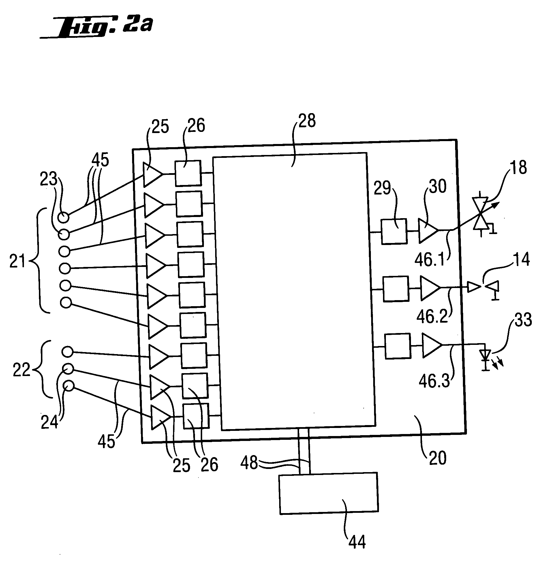
[0009] In an advantageous further development, the device for pattern recognition comprises preamplifier devices by which the signals emitted by the sensors are electronically amplified and conveyed to the A / D converter of the device for pattern recognition in which the measurement data of the sensors which are in analog form are converted into digital data. The A / D converters are connected on the output side to the data processing unit of the device for pattern recognition. A neuronal network for evaluating the measurement data pattern is advantageously emulated in the data processing unit. A very quickly and accurately working monitoring system can be achieved by emulation of the neuronal network in the data processing unit and the processing of digitized data. The neuronal network emulated in the data processing unit, e.g., the microprocessor, has the advantage over an analog neuronal network that the device for pattern recognition occupies relatively little space and that the stored parameters are stable over a long period of time and are not susceptible to interference.
[0011] Further, it is advantageous when the data processing unit has a read-only memory in which the parameter data patterns needed for evaluating and categorizing the measurement data patterns are stored.
[0012] In an advantageous variant of the setting device according to the invention, the sensors are constructed as magnetic sensors, wherein at least one magnetic field source such as a permanent magnet or an electromagnet is arranged at the guide. The magnetic sensors pick up a magnetic stray flux which proceeds from the piston or from one or more fastening elements located in the pin guide. The magnetic sensors can be Hall sensors. Sensor arrays of this type comprising magnetic sensors can be realized in a simple manner technologically and result in an economical setting device which can be manufactured relatively advantageously.
[0013] In another advantageous variant of the setting device, the sensors are constructed as capacitive sensors. This has the advantage over magnetic sensors in that an electromagnetic magnetic field source need not be provided at the device in addition to a power source.
[0016] Further, it can also be advantageous when the processed measurement signals are changed back into analog form by D / A converters and amplified by output amplifier devices after passing through the final signal processing stage of at least one signal processing stage. Subsequently, the signals can be outputted at adjusting devices, ignition devices, valve devices and / or display devices and used to control the device (e.g., to switch off the setting device) or to convey information about the state of the device to the user of the setting device (e.g., an alert that the piston must be exchanged due to wear).

Problems solved by technology

It is, however, disadvantageous in this known solution that wear cannot be detected in wearing parts such as the piston guide, the pin guide, the driving piston or the like.
Further, the jam detector can detect the presence of a fastener jam only quantitatively, but cannot determine qualitatively the kind of jam.

Method used


Image

  • Setting device
  • Setting device
  • Setting device

Examples


Embodiment Construction

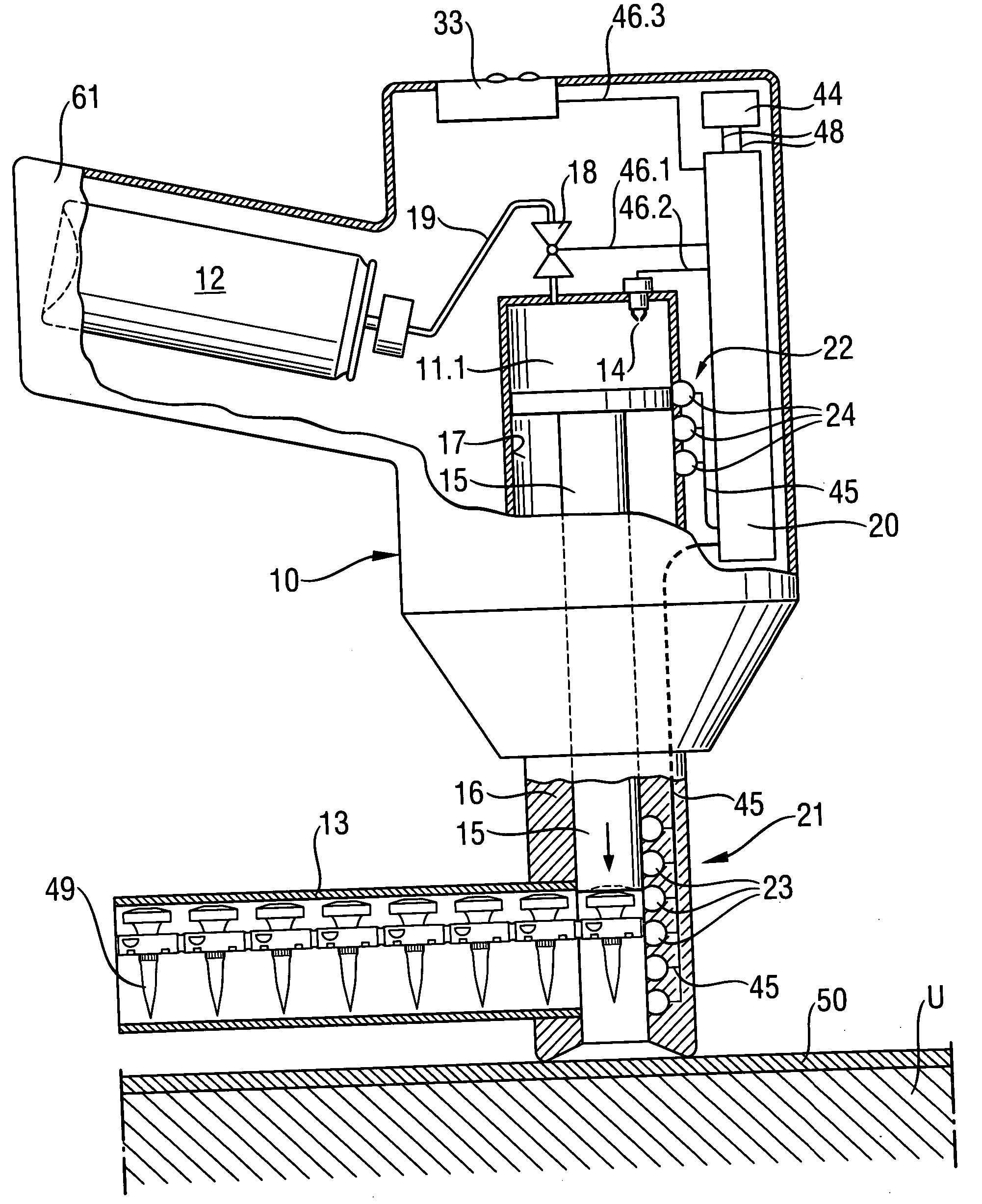
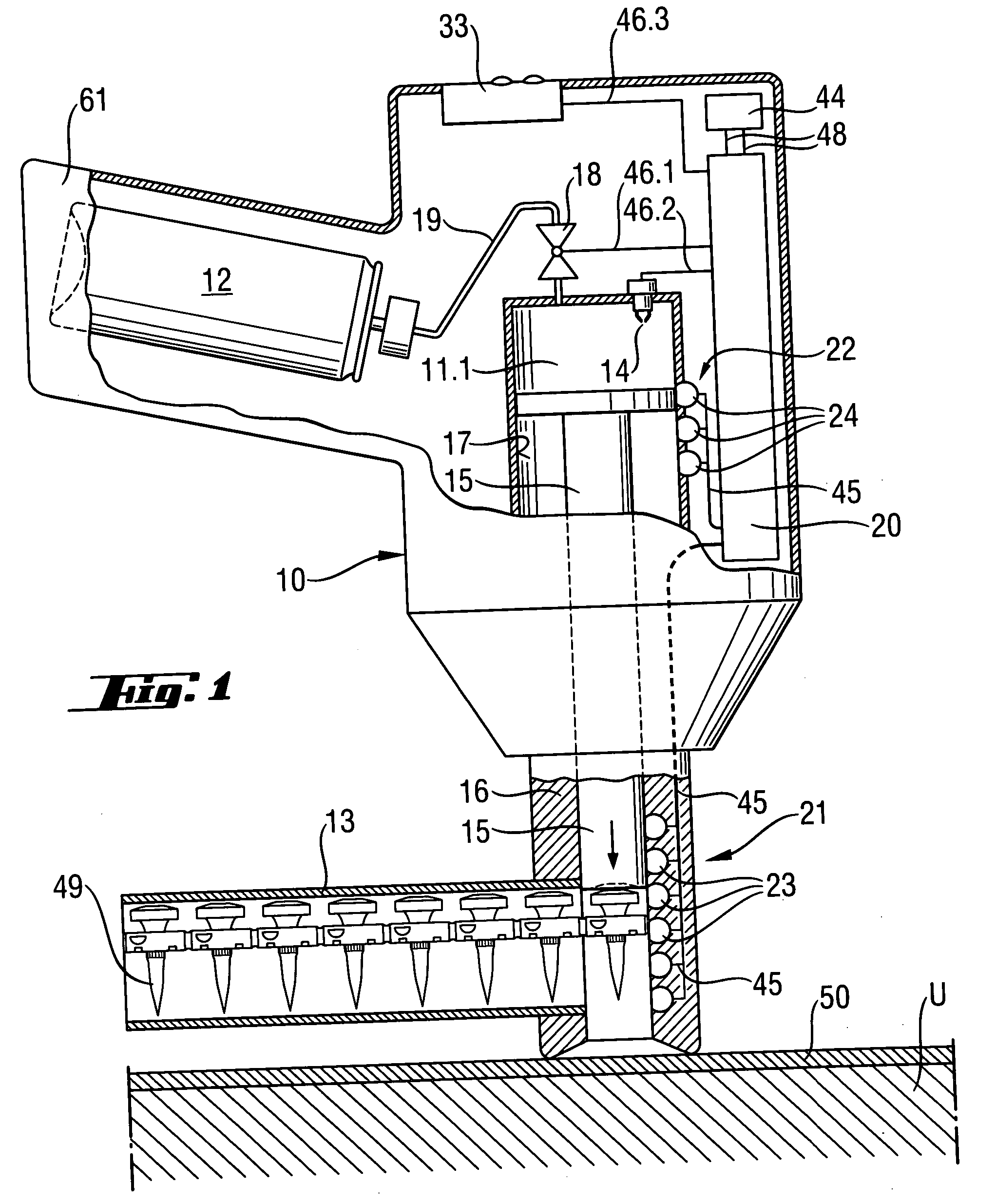
[0026]FIG. 1 shows a combustion-operated setting device according to the, invention that is pressed against a substrate U upon which a structural component part 50, such as a metal sheet, is to be fastened. The setting device has a housing 10 with a handle 61 formed thereon. Located at the handle 61 is a trigger switch, not shown, by which a setting process can be initiated. Further, the setting device has a combustion chamber 11.1 and a piston guide 17 in which a driving piston 15 is movably guided. Adjoining the piston guide 17 in setting direction is a pin guide 16. A magazine 13 for fastening elements 49 is arranged at the front end of the pin guide 16. A propellant vessel 12 is arranged in the handle 61 of the setting device, particularly in an exchangeable manner, and in the present embodiment example is a vessel for a liquid fuel, e.g., liquid gas, under pressure. The propellant vessel 12 is connected via a fuel feed 19, such as a fuel line, to a valve device 18, e.g., a mete...


PUM

PropertyMeasurementUnit
magnetic fieldaaaaaaaaaa
electrically conductingaaaaaaaaaa
magnetic stray fluxaaaaaaaaaa

Abstract

The present invention is directed to a combustion-operated setting device for driving fastening elements such as nails, bolts and pins into a substrate, with a setting mechanism comprising a driving piston (15) which is supported to be displaceable in a guide, and with an electronic monitoring device for monitoring the status of the setting device. At least one sensor array (21, 22) is arranged at the guide for generating a measurement data pattern which can be evaluated by the monitoring device.

Description

BACKGROUND OF THE INVENTION [0001] The present invention is directed to a setting device for driving fastening elements such as nails, bolts and pins into a substrate, with a setting mechanism comprising a driving piston displaceable in a guide, and an electronic monitoring device for monitoring the status of the setting device, wherein at least one sensor array is arranged at the guide for generating a measurement data pattern that can be evaluated by the monitoring device. The invention is also directed to a method for detecting wear in wearing parts of a combustion-operated setting device. Setting devices of this kind, particularly combustion-operated setting devices or setting devices operating on compressed air, are used to drive fastening elements into a substrate. [0002] In general, it is desirable in setting devices of this type to make the setting device as user-friendly as possible. [0003] U.S. Pat. No. 6,123,241 discloses a combustion-operated setting device with a monito...

Claims


Application Information

Patent Timeline
Patent Type & Authority Applications(United States)
IPC IPC(8): B25C1/08B25C1/14B25C7/00
CPCB25C1/14B25C1/08
Inventor FAVRE-BULLE, BERNARDSCALET, MARIOGANTNER, GEBHARD
Owner HILTI AG
Why Eureka
Eureka Blog
Learn More