
Reusable pull rod type quick locking device

A technology of locking device and pull rod, applied in the direction of workpiece clamping device, manufacturing tools, etc., to achieve strong adaptability, improve fastening efficiency, and reduce the difficulty of locking

Pending Publication Date: 2022-02-08
重庆交通大学绿色航空技术研究院 +1
View PDF8 Cites 0 Cited by
  • Summary
  • Abstract
  • Description
  • Claims
  • Application Information

AI Technical Summary

Problems solved by technology

[0005] The purpose of the present invention is to provide a reusable pull rod type quick locking device to solve the shortcomings of the existing locking structure in view of the above existing problems

Method used


Image

  • Reusable pull rod type quick locking device
  • Reusable pull rod type quick locking device
  • Reusable pull rod type quick locking device

Examples


Embodiment 1

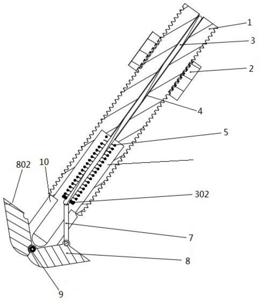
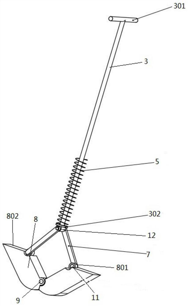
[0027] A reusable pull rod type quick locking device, comprising a stud 1, the stud 1 has a cylindrical structure as a whole, such as figure 1 and figure 2 As shown, the outer surface of the stud 1 is provided with an external thread 101, and the external thread 101 is mainly used for connecting the lock nut 2, that is, the lock nut 2 is sleeved on the stud 1 and is threaded. In practical applications, along the axial direction of the stud 1, the distribution length of the external thread 101 is not only related to the moving distance of the lock nut 2, but also can be determined according to the properties of the through holes on the locked sealing member (not shown). To design, for example, when the threaded connection between the stud 1 and the through hole on the locked sealing member is required, the distribution length of the external thread 101 of the stud 1 can be extended, and even the outer surface of the stud 1 can be extended. All are wrapped by external threads ...

Embodiment 2

[0035] This embodiment is the same as Embodiment 1, the difference is that the end surface of the stud 1 opposite to the brake rod 301 is provided with a brake rod groove 102 for accommodating the brake rod 301, as Figure 4 As shown, the length of the brake rod 301 is greater than the length of the brake rod slot 102 .

Embodiment 3

[0037] This embodiment is the same as Embodiment 1, the difference is that the rod through hole 4 is threadedly connected with the locking rod 3, and the locking rod 3 is rotationally connected with the bushing 12 (not shown in the figure out). In this embodiment, this embodiment mainly considers that during the process of placing the locking device in the through hole of the locking sealing member, it is necessary to keep the pull rod lifted, which may cause inconvenience to the locking operation. For this reason, through The threaded connection between the locking rod 3 and the rod through hole 4 can accurately adjust the lifting distance of the locking rod 3, even if the locking rod 3 is not pulled, the lifting state can be maintained to facilitate the locking device Perform related operations.


PUM


Abstract

The invention discloses a reusable pull rod type quick locking device which comprises a stud, the stud is sleeved with a locking nut, the locking nut is in threaded connection with the stud, a pull rod through hole is formed in the stud, one end of the stud is concaved inwards to form a containing groove used for containing an elastic piece, and the pull rod through hole penetrates through the stud. The locking pull rod penetrates through the stud, a brake rod is arranged at one end of the locking pull rod, the other end of the locking pull rod is hinged to the locking block mechanism through a connecting rod, the brake rod is limited outside the stud through the end face of the stud, the locking block mechanism comprises two locking blocks hinged to each other, and the locking blocks are hinged to the locking pull rod through the connecting rod. And when the locking pull rod moves along the pull rod through hole, the two mutually hinged locking blocks rotate around a hinge point of the locking blocks. According to the locking device, the fastening efficiency is improved, the locking difficulty of the sealing component is reduced, repeated use can be achieved, the adaptability to the component structure is high, the locking effect is outstanding, and locking operation is easy.

Description

technical field [0001] The invention relates to the technical field of seal connection, in particular to a reusable pull rod type quick locking device. Background technique [0002] When two components are fixedly connected and one of them is a sealing component, the bolt connection can only fix the bolts on the sealing end component, and cannot realize secondary utilization. Moreover, when one end of the component cannot be operated well, use the bolt to fix the component. When one side is fastened, the other side will rotate at the same time, which cannot achieve the effect of fixing the component well. If nails or riveting are used for fastening, the nails and riveting components cannot be reused, which wastes workpiece resources. [0003] Chinese patent CN207231686U discloses an on-line detection device for spring buckle pressure and its pre-clamping and labor-saving lifting mechanism. Nut 18, the outer nut 5 that is connected with the inner nut 18, the pre-clamping lif...

Claims


Application Information

Patent Timeline
IPC IPC(8): B25B11/00
CPCB25B11/00
Inventor 王希理胥树霖于洋陈全龙郑博睿居婷毛跃鹏彭阳
Owner 重庆交通大学绿色航空技术研究院
Learn More