
An oil pipe fastener and method thereof

A technology of fasteners and oil pipes, which is applied in the direction of manufacturing tools, workpiece clamping devices, etc., can solve the problems of unreliability, labor consumption, reduction of plastic hardness and flexibility, avoid slipping, improve efficiency and reliability, and quickly The effect of tightening and releasing

Active Publication Date: 2021-04-09
ELECTRIC POWER RES INST OF EAST INNER MONGOLIA ELECTRIC POWER +1
View PDF7 Cites 0 Cited by
  • Summary
  • Abstract
  • Description
  • Claims
  • Application Information

AI Technical Summary

Problems solved by technology

The manual method is labor-intensive and unreliable, and it is very difficult for operators to work when the weather is very cold; at the same time, the hardness and flexibility of the plastic straps are reduced when the weather is cold in the north, and they are easy to break during the strapping process. In addition, the diameter of some transformer oil drains is about 6mm. , the straps cannot be tightened due to structural limitations

Method used


Image

  • An oil pipe fastener and method thereof
  • An oil pipe fastener and method thereof
  • An oil pipe fastener and method thereof

Examples


Embodiment 1

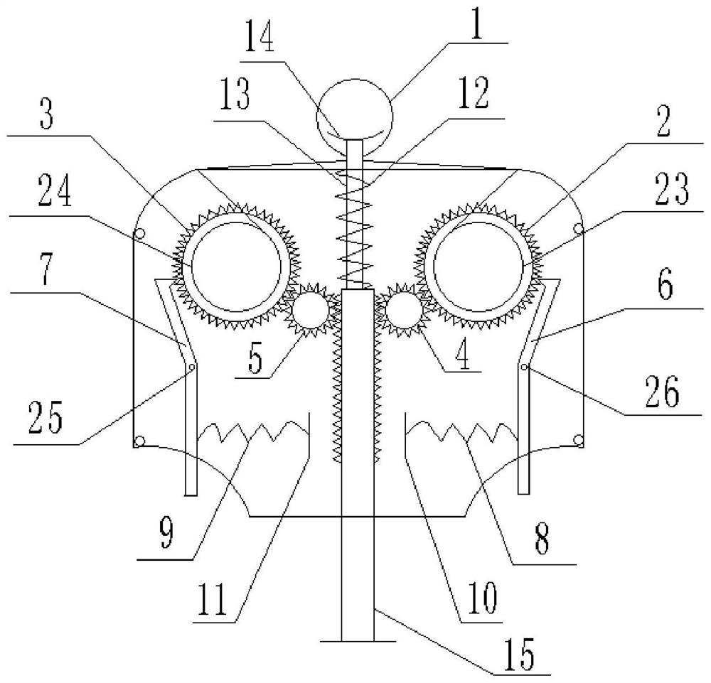
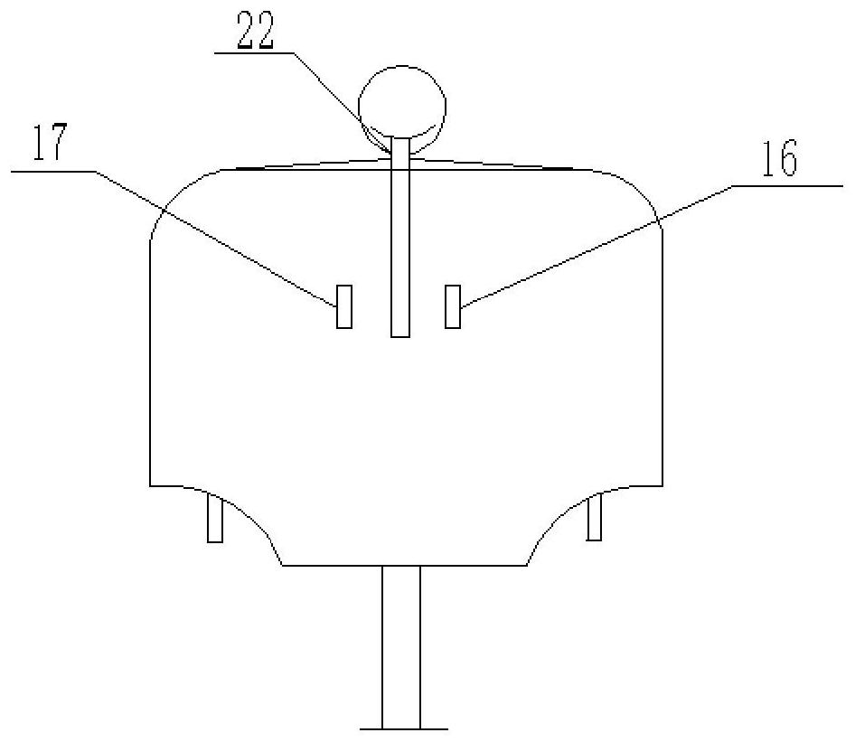
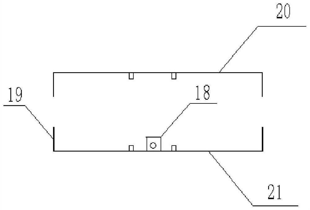
[0049] Such as Figure 1-4 As mentioned above, Embodiment 1 of the present disclosure provides an oil pipe fastener, including a stainless steel wire 1 with a diameter of 0.5 mm, a gear, a toothed push rod 15 and a fastener body, and the toothed push rod 15 is square Plastic push rod, the gears include the first gear 2, the second gear 3, the third gear 4 and the fourth gear 5 arranged inside the fastener body, the first gear 2 is fixed with a first coil 23 , the first gear 2 is fixed with a first reel 23 to rotate coaxially, the second gear 3 is fixed with a second reel 24, and the second gear 3 is fixed with a second reel 24 to rotate coaxially. Both the first gear 2 and the second gear 3 are circular hollow structures, one end of the stainless steel wire 1 is fixedly connected to the first coil 23 through the first through hole on the fastener body, and the other end is passed through the fastening The second through hole on the device body is fixedly connected with the se...

Embodiment 2

[0066] Such as Figure 5 As shown, Embodiment 2 of the present disclosure provides a method for fastening an oil pipe, and the steps are as follows:

[0067] Put the oil pipe into the steel traveler, put the oil pipe on the oil outlet, adjust the fastener steel wire to the proper position of the oil pipe, hold the fastener with your hand, push the toothed push rod, and the first spring is compressed;

[0068] The pushing process of the toothed push rod drives the third gear and the fourth gear to rotate, thereby driving the first gear and the second gear to rotate, and the steel wire is coiled by the first and second coils.

[0069] After the toothed push rod is fully pressed, release the toothed push rod, the first spring rebounds from the compression, driving the toothed push rod to reset, the third gear and the fourth gear slide along the first slide rail and the second slide rail respectively , separated from the first gear and the third gear, the toothed push rod is rese...


PUM


Abstract

The present disclosure provides an oil pipe fastener and a method thereof, including a metal wire, a gear, a toothed push rod and a fastener body, wherein the gear includes a first gear and a second gear disposed inside the fastener body, The first reel is fixed on the first gear, the second reel is fixed on the second gear, and one end of the wire passes through the first through hole on the fastener body and is fixedly connected to the first reel, The other end passes through the second through hole on the fastener body and is fixedly connected to the second coil to form a crossed circular or elliptical wire loop; the first gear and the second gear are symmetrically arranged on the toothed push rod respectively. On both sides, by pushing the toothed push rod to drive the first coil and the second coil on the first gear and the second gear to rotate, tighten the metal wire; it can realize the tightening work of the oil pipes of all voltage level transformers at present, and avoid When taking oil, the oil pipe slips down, which improves the efficiency and reliability of transformer insulating oil sampling work.

Description

technical field [0001] The present disclosure relates to the field of fastening technology, in particular to a fastening device and method for an oil pipe. Background technique [0002] The statements in this section merely provide background information related to the present disclosure and may not necessarily constitute prior art. [0003] According to the requirements of GBT7597 "Electric Power Oil (Transformer Oil, Turbine Oil Sampling Method"), in the determination of the moisture content in the power transformer insulating oil and the analysis of dissolved gas in the oil, the sampling of the transformer insulating oil is to use the oil pipe from the oil discharge port of the transformer. Lead out the insulating oil inside the transformer, put the oil pipe on the outside of the oil inlet of the transformer, unscrew the oil release valve, and use a syringe to collect the transformer oil sample at the other end of the oil pipe. According to the requirements of the above r...

Claims


Application Information

Patent Timeline
Patent Type & Authority Patents(China)
IPC IPC(8): B25B11/00
CPCB25B11/00
Inventor 安义岩郭金刚王延伟左秀江党乐王钰秘立鹏佟敏陈雅琦胡志帅李博刘慧张小明周丽英尚鑫万润楠
Owner ELECTRIC POWER RES INST OF EAST INNER MONGOLIA ELECTRIC POWER
Learn More