Electronically controlled shift device for new energy vehicles
A new energy vehicle and shifting device technology, applied in transmission, gear transmission, transmission control and other directions, can solve problems such as difficult shifting and deceleration, brake disc overheating, induction, etc., to protect driving safety and ensure braking performance effect
- Summary
- Abstract
- Description
- Claims
- Application Information
AI Technical Summary
Problems solved by technology
Method used
Image
Examples
Embodiment 1
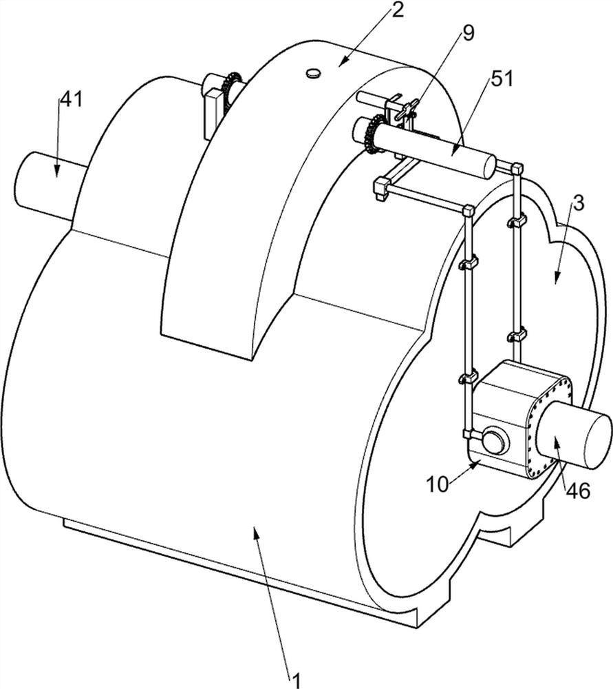
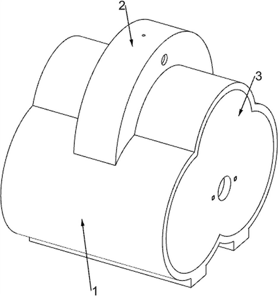
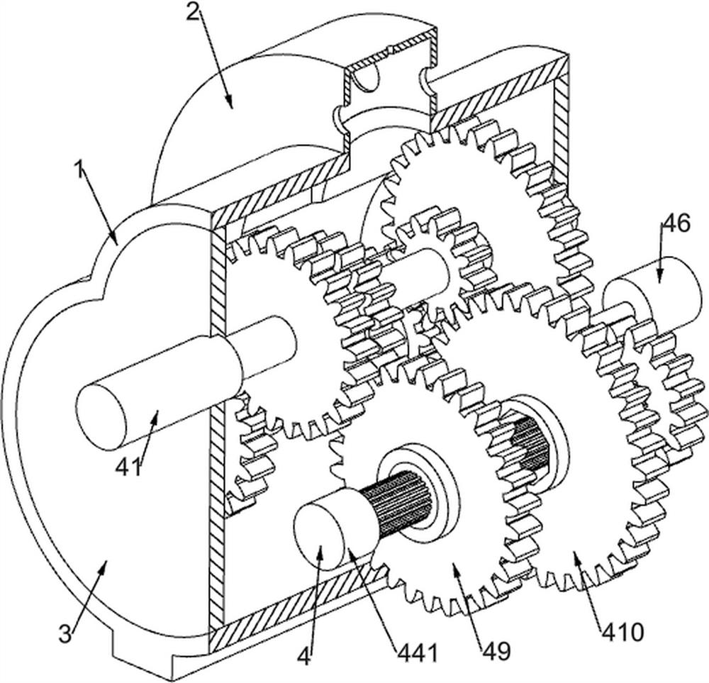
[0037] Electronically controlled shifting devices for new energy vehicles, such as Figure 1-11 As shown, it includes a bottom frame 1, an arc-shaped protective frame 2, a cover plate 3, a rotating assembly 4, a manual shift assembly 5 and a sliding sleeve assembly 6. The top of the bottom frame 1 is fixedly installed with an arc-shaped protective frame 2, and the bottom frame 1 A cover plate 3 is fixedly installed on both sides, and a rotating assembly 4 is jointly connected to the two cover plates 3 in a rotating manner. The gear assembly 5 is used for shifting the vehicle, and the sliding sleeve assembly 6 is arranged on the rotating assembly 4 .
[0038] The rotating assembly 4 includes an input shaft 41, a first transmission gear 42, a second transmission gear 43, a third transmission gear 431, a fourth transmission gear 44, a spline shaft 441, a connecting gear 45, an output gear shaft 46, a spline gear sleeve 1 47, Spline gear sleeve two 48, spline gear sleeve three 49...
Embodiment 2
[0046] On the basis of Example 1, as Figure 8 As shown, it also includes a limit assembly 7, the top of the arc-shaped protection frame 2 is slidably connected to a limit assembly 7, the limit assembly 7 is used to limit the transmission lever 51, and the limit assembly 7 includes a slotted limit wheel 71. The clamping rod 72 and the second return spring 73, the transmission lever 51 is fixedly connected with a slotted limit wheel 71, the top of the arc protection frame 2 is slidably connected with a clamping rod 72, and the clamping rod 72 is connected with the slotted limit wheel. 71 contacts, the clamping rod 72 is used to clamp the slotted limit wheel 71, and a second return spring 73 is connected between the clamping rod 72 and the arc-shaped protection frame 2.
[0047] The rotation of the transmission lever 51 will drive the slotted limit wheel 71 to rotate, and the slotted limit wheel 71 will push the clamping rod 72 to move upward, and then the compressed second retu...
Embodiment 3
[0049] On the basis of Example 1, as Figure 9-10 As shown in the figure, it also includes an uphill and downhill electronically controlled shifting assembly 8, the top of the bottom frame 1 is fixedly installed with an uphill and downhill electronically controlled shifting assembly 8, and the uphill and downhill electronically controlled shifting assembly 8 is used for shifting adjustment when going up and downhill, The uphill and downhill electronically controlled shifting assembly 8 includes an I-shaped support frame 81, a speed sensor 82, two adjusting gears A, two overrunning clutches A, an arc slotted frame 85, a sliding rack frame 86, an electromagnetic block 87 and The first return spring 88, the cover plate 3 on the left side is fixedly installed with the I-shaped support frame 81 on the right side, the I-shaped support frame 81 is fixedly installed with three speed sensors 82, the input shaft 41 penetrates the upper speed sensor 82, the spline The shaft 441 runs thro...
PUM
 Abstract
Description
Claims
Application Information
 - R&D
- Intellectual Property
- Life Sciences
- Materials
- Tech Scout
- Unparalleled Data Quality
- Higher Quality Content
- 60% Fewer Hallucinations
Browse by: Latest US Patents, China's latest patents, Technical Efficacy Thesaurus, Application Domain, Technology Topic, Popular Technical Reports.
© 2025 PatSnap. All rights reserved.Legal|Privacy policy|Modern Slavery Act Transparency Statement|Sitemap|About US| Contact US: help@patsnap.com


