Electric control gear shifting device for new energy vehicle

A technology of new energy vehicles and shifting devices, which is applied in the direction of transmission, gear transmission, transmission control, etc. It can solve the problems of difficult shift deceleration, brake disc overheating, difficult shift precise control, etc., to protect driving safety , to ensure the effect of braking performance

Active Publication Date: 2022-02-08
HANGZHOU JIAMIAO TECH SERVICE CO LTD
View PDF13 Cites 0 Cited by
  • Summary
  • Abstract
  • Description
  • Claims
  • Application Information

AI Technical Summary

Problems solved by technology

[0003] Since the existing electronically controlled shifter realizes the operation lever to control the shifting operation through the card slot design of the panel, when it is necessary to overtake on an uphill, downhill, long slope or at a high speed per hour, the signals of each sensor cannot be used for each gear. It is difficult for novice drivers to accurately control the shifting during the shifting process, and it is difficult to achieve fast shifting and deceleration. Novice drivers will decelerate through the brakes. Using the brakes over time can overheat the discs and cause the brakes to fail

Method used


Image

  • Electric control gear shifting device for new energy vehicle
  • Electric control gear shifting device for new energy vehicle
  • Electric control gear shifting device for new energy vehicle

Examples


Embodiment 1

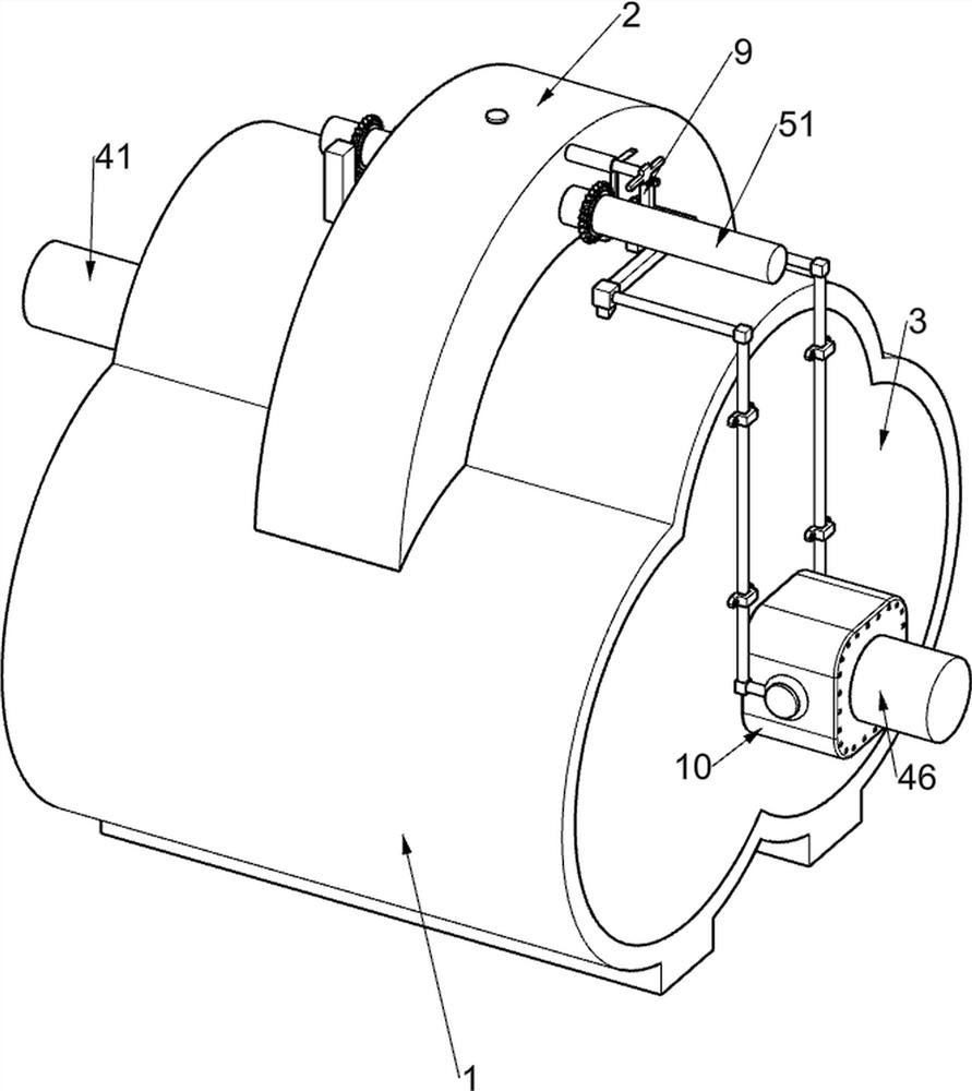
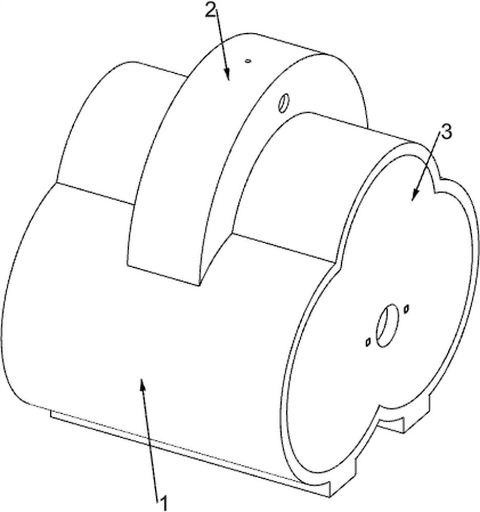
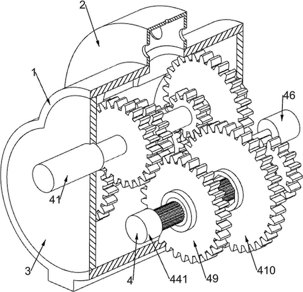
[0037] Electronically controlled shifting devices for new energy vehicles, such as Figure 1-11 As shown, it includes a bottom frame 1, an arc-shaped protection frame 2, a cover plate 3, a rotating assembly 4, a manual shift assembly 5, and a sliding sleeve assembly 6. The top of the bottom frame 1 is fixedly installed with an arc-shaped protection frame 2, and the bottom frame 1 Cover plates 3 are fixedly installed on both sides. The two cover plates 3 are jointly rotatably connected with a rotating assembly 4. The engine drives the car through the rotating assembly 4. The arc protection frame 2 is rotatably connected with a manual shift assembly 5. The gear assembly 5 is used for shifting gears of the automobile, and the sliding sleeve assembly 6 is arranged on the rotating assembly 4 .

[0038] Rotating assembly 4 includes input shaft 41, transmission gear one 42, transmission gear two 43, transmission gear three 431, transmission gear four 44, spline shaft 441, connecting ...

Embodiment 2

[0046] On the basis of Example 1, such as Figure 8 As shown, it also includes a limit assembly 7, the top of the arc protection frame 2 is slidingly connected to the limit assembly 7, the limit assembly 7 is used to limit the transmission lever 51, and the limit assembly 7 includes a slotted limit wheel 71, clamping lever 72 and second reset spring 73, slotted limit wheel 71 is fixedly connected on the transmission lever 51, and clamping lever 72 is slidably connected to the top of the arc protection frame 2, and clamping lever 72 is connected with the slotted limiting wheel 71 contacts, the clamping rod 72 is used to clamp the slotted limit wheel 71 , and a second return spring 73 is connected between the clamping rod 72 and the arc protection frame 2 .

[0047] The rotation of the transmission lever 51 will drive the slotted limiting wheel 71 to rotate, and the slotted limiting wheel 71 will push the clamping rod 72 to move upwards, and then the compressed second return spr...

Embodiment 3

[0049] On the basis of Example 1, such as Figure 9-10 As shown, it also includes an uphill and downhill electronically controlled shifting assembly 8. The uphill and downhill electronically controlled shifting assembly 8 is fixedly installed on the top of the bottom frame 1. The uphill and downhill electric control shift assembly 8 includes an I-shaped support frame 81, a speed sensor 82, an adjustment gear 83, an overrunning clutch 84, an arc slotted frame 85, a sliding rack frame 86, an electromagnetic block 1 87 and a first homing Spring 88, the right side of the cover plate 3 on the left is fixedly installed with an I-shaped support frame 81, and three speed sensors 82 are fixedly installed on the I-shaped support frame 81, the input shaft 41 runs through the top speed sensor 82, and the spline shaft 441 runs through the bottom Two speed sensors 82, the speed sensor 82 is used to detect the gap between the rotation speed of the key shaft 441 and the output speed of the in...


PUM


Abstract

The invention relates to the field of new energy vehicles, in particular to an electric control gear shifting device for a new energy vehicle. The device comprises a bottom frame, an arc-shaped protection frame, cover plates, a rotating assembly, a manual gear shifting assembly and the like; and an arc-shaped protection frame is fixedly installed on the top of the bottom frame, the cover plates are fixedly installed on the two sides of the bottom frame, the two cover plates are jointly and rotationally connected with the rotating assembly, and the arc-shaped protection frame is rotationally connected with the manual gear shifting assembly. When overtaking is needed on a long slope or at a high speed per hour, a transmission deflector rod can be controlled to change the rotating direction, the moving direction of a convex circular ring and the moving direction of devices on the convex circular ring can be adjusted, gear reduction is conducted on an automobile to reduce the speed of the automobile, the braking performance is guaranteed, and the situation that braking failure is caused by overheating of a brake disc when a brake is used for a long time is avoided.

Description

technical field [0001] The invention relates to the field of new energy vehicles, in particular to an electronically controlled shifting device for new energy vehicles. Background technique [0002] With the development of the shifter industry, electronically controlled shifters have become more and more popular, and the so-called electronically controlled shifters refer to touching the sensors located in various positions through the toggle of the operating lever, thus The signals of each sensor correspond to each gear position, and the shift mechanism is driven by a motor to drive the shift fork to move the synchronizer gear sleeve, so that the synchronizer gear sleeve cooperates with the driving gear of the corresponding gear position to realize the shift operation. The operating lever of the control shifter is reset to the N position after each toggle. [0003] Since the existing electronically controlled shifter realizes the operation lever to control the shifting oper...

Claims


Application Information

Patent Timeline
Patent Type & Authority Applications(China)
IPC IPC(8): F16H3/32F16H57/02F16H63/30F16H61/02F16H61/18F16H59/70
CPCF16H3/32F16H57/02F16H63/30F16H61/0204F16H61/18F16H59/70F16H2063/3096F16H2061/205
Inventor 江应林
Owner HANGZHOU JIAMIAO TECH SERVICE CO LTD
Why Eureka
Try Eureka