Equipment noise source imaging method and device, electronic equipment and storage medium

An imaging method and sound source technology, which are applied to frequency/directional characteristic devices, measuring devices, electrical components, etc., and can solve problems such as limited imaging range.

Pending Publication Date: 2022-02-08
北京华控智加科技有限公司
View PDF5 Cites 4 Cited by
  • Summary
  • Abstract
  • Description
  • Claims
  • Application Information

AI Technical Summary

Problems solved by technology

However, as a small microphone array, the acoustic imager has a very limited imaging range

Method used


Image

  • Equipment noise source imaging method and device, electronic equipment and storage medium
  • Equipment noise source imaging method and device, electronic equipment and storage medium
  • Equipment noise source imaging method and device, electronic equipment and storage medium

Examples


Embodiment Construction

[0060]The following will clearly and completely describe the technical solutions in the embodiments of the application with reference to the drawings in the embodiments of the application. Apparently, the described embodiments are only some of the embodiments of the application, not all of them. Based on the embodiments in the present application, all other embodiments obtained by persons of ordinary skill in the art without making creative efforts belong to the protection scope of the present application.

[0061] The imaging method of equipment noise sound source according to an embodiment of the present disclosure may include the following steps:

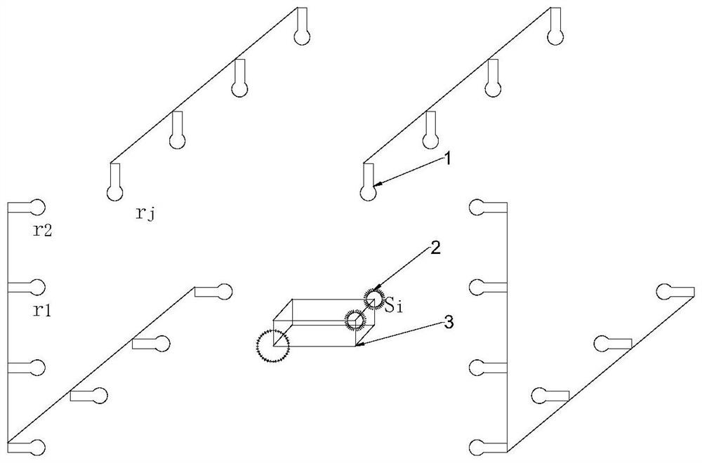
[0062] In step 1, a multi-microphone synchronous sound acquisition system is designed to synchronously collect the imaging point noise signal of the device under test through multiple microphones.

[0063] In one embodiment, the multi-microphone synchronous sound collection system includes M microphones, the M microphones are pla...


PUM


Abstract

The invention belongs to the technical field of equipment state monitoring methods and technologies and fault positioning, and particularly relates to an equipment noise source imaging method and device, electronic equipment and a storage medium. The invention discloses an equipment noise source imaging method. The method comprises the following steps: firstly, designing a multi-microphone synchronous sound acquisition system; generating a relation table of sound transmission distance and sound transmission time between the microphone and the to-be-tested equipment; and acquiring a noise signal of the to-be-detected equipment, and calculating the intensity of the noise signal of an imaging point to obtain an image of an equipment noise source. According to the invention, a plurality of microphone devices which are arranged on the outer wall of industrial large-scale equipment or in a large-scale equipment working place and are used for synchronously collecting are combined into a large-scale microphone array, and a sound array imaging algorithm is used for carrying out full-space sound imaging on the interior of the equipment or the equipment working place. A visualization technology is used for displaying noise excitation intensities of components in the equipment or different positions in the space so as to be used for equipment operation state monitoring and fault positioning.

Description

technical field [0001] The present application belongs to the field of equipment state monitoring method technology and fault location technology, and in particular relates to an equipment noise sound source imaging method, device, electronic equipment and storage medium. Background technique [0002] In the field of equipment condition monitoring and fault diagnosis, the vibration and noise of equipment components are the most commonly used monitoring values ​​and analysis parameters. Changes in the intensity of vibration and noise can indicate the health status of the equipment, and changes in the vibration spectrum can indicate the location of the fault. For example, the most common gears and bearings in equipment, the vibration spectrum lines of the same gear or bearing in the normal state at the same speed are very similar. When the energy of a spectral line is abnormal or there is a spectral line that does not exist in the normal state, it is often If a component fail...

Claims


Application Information

Patent Timeline
Patent Type & Authority Applications(China)
IPC IPC(8): G01M13/028G01M13/045H04R1/40
CPCG01M13/028G01M13/045H04R1/406
Inventor 刘加卢回忆刘豪睿曹宏刘德广
Owner 北京华控智加科技有限公司
Why Eureka
Try Eureka