Matrix surround decoder/virtualizer

a matrix surround and virtualizer technology, applied in the field of audio signal processing, can solve the problems of decoding dolby encoded audio materials, inability to place speakers, and limited resources of listeners,

Inactive Publication Date: 2006-02-21
QSOUND LABS
View PDF14 Cites 39 Cited by
  • Summary
  • Abstract
  • Description
  • Claims
  • Application Information

AI Technical Summary

Benefits of technology

[0010]A technical advantage of the present invention is to separately operate on center, surround, and stereo information contained within a matrix encoded stereo input signal.
[0011]Another technical advantage of the present invention is that center information contained within the stereo input signal is retained during processing of the input signal.
[0012]A further technical advantage of the present invention is that ma

Problems solved by technology

A problem with existing systems is that a listener has to use more than two speakers to get the desired surround effect from a sound source.
Thus, listeners with limited resources are not able to afford the multiple speaker systems or are unable to find means for placing the speakers to achieve the desired sound effects.
Another problem occurs when Dolby encoded audio materials are decoded on QSound

Method used


Image

  • Matrix surround decoder/virtualizer
  • Matrix surround decoder/virtualizer
  • Matrix surround decoder/virtualizer

Examples


Embodiment Construction

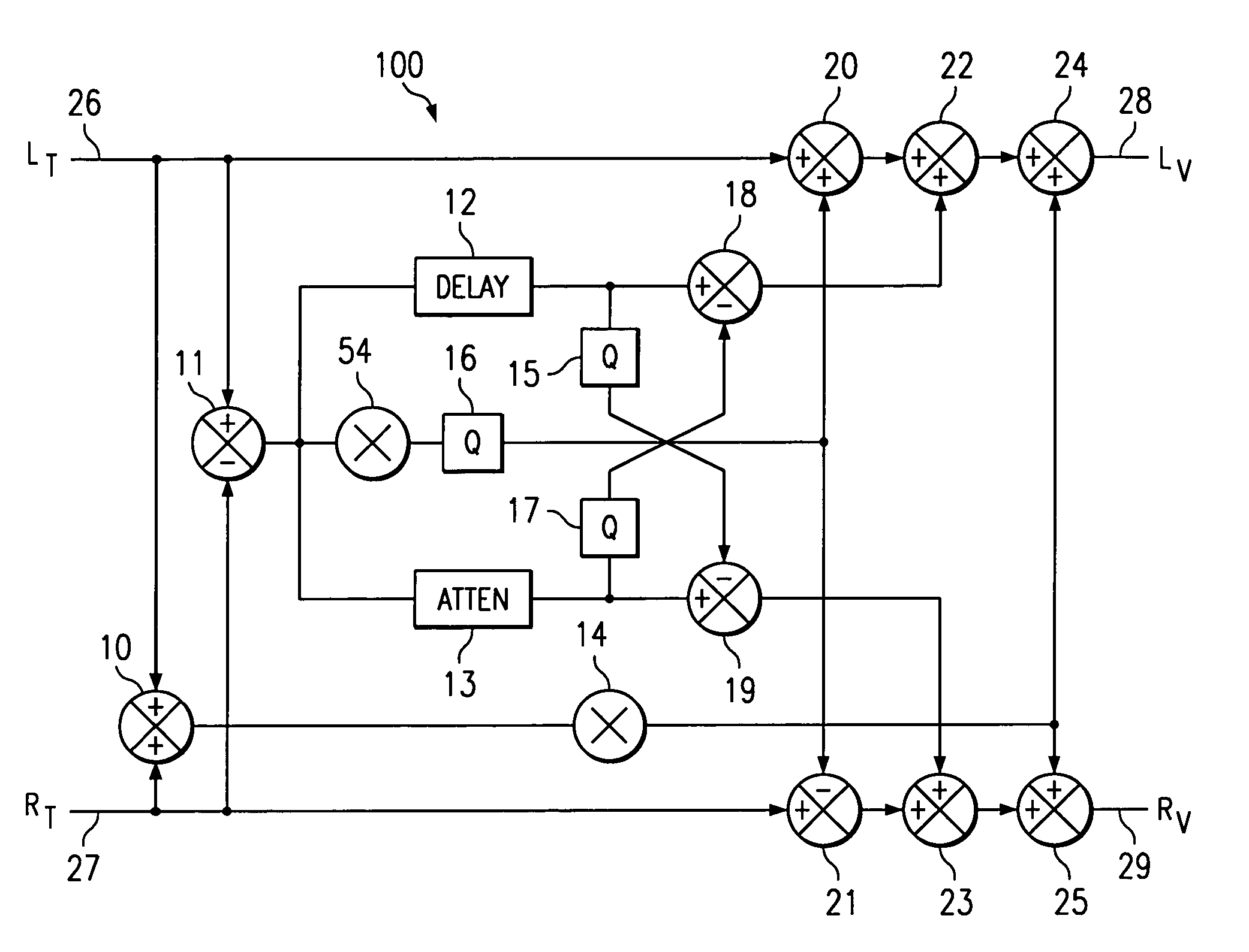
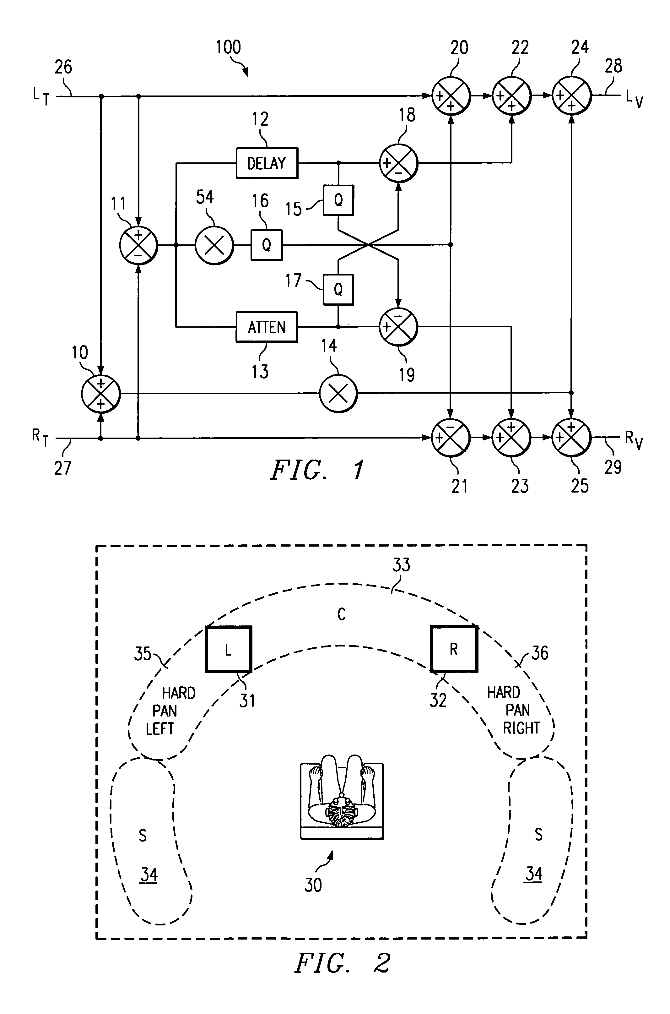
[0019]FIG. 1 depicts a preferred embodiment of the inventive mechanism. In the inventive arrangement 100 of FIG. 1, a two-channel stereo input from an A / V source, which includes encoded surround information, is converted into output signals. Left input 26 and right input 27 include four different signal portions-left, right, center, and surround. The input signals are processed into left output 28 and right output 29. Although only two outputs are shown, other outputs can be provided for rear or surround channels, a center channel, and / or a sub-woofer channel. The inventive arrangement 100 of FIG. 1 is subdivided into three sub-systems.

[0020]The first sub-system is used to provide a phantom center output. As shown in FIG. 2, the sound image of the phantom center location 33 appears to listener 30 to be placed between left 31 and right 32 speakers. Note that the left and right speakers are connected to left output 28 and right output 29 of FIG. 1, respectively. This sub-system may in...


PUM


Abstract

The inventive mechanism uses several sub-systems to generate outputs from the stereo input signal. A first sub-system synthesizes the phantom center output, which places the monaural center image between the left and right speakers in front of the listener. A second sub-system synthesizes the virtual surround (or rear) output signals, which places the sound images to the sides of the listener. A third sub-system synthesizes the left and right stereo outputs, and expands the locations of the left and right sound images.

Description

RELATED APPLICATIONS[0001]The present application is a continuation-in-part of and commonly assigned U.S. application Ser. No. 09 / 058,047 now U.S. Pat. No. 6,198,826, entitled QSOUND SURROUND SYNTHESIS FROM STEREO filed Apr. 9, 1998, which is incorporated herein by reference, which is a continuation-in-part of and commonly assigned U.S. application Ser. No. 08 / 858,586 now U.S. Pat. No. 6,126,730, entitled FULL SOUND ENHANCEMENT USING MULTI-INPUT SOUND SIGNALS filed May 19, 1997, which is incorporated herein by reference. The present application is related to co-pending and commonly assigned U.S. application Ser. No. 08 / 858,594, entitled METHOD AND SYSTEM FOR SOUND EXPANSION, filed May 19, 1997, which is incorporated herein by reference. The present application is related to commonly assigned U.S. Pat. No. 5,105,462, issued to Lowe, et al, entitled SOUND IMAGING METHOD AND APPARATUS, filed May 2, 1991, and issued Apr. 14, 1992, the disclosure of which is incorporated herein by refere...

Claims


Application Information

Patent Timeline
IPC IPC(8): H04R5/00
CPCH04S3/02H04S2400/01
Inventor ARTHUR, JOHN ERIC
Owner QSOUND LABS
Why Eureka
Try Eureka