
Platform circulation supply type lamination production line and circulation lamination process thereof

One-type lamination and production line technology, applied in the field of platform circulation supply lamination production line and its circulation lamination process, can solve the problems that the positions of pole pieces and diaphragms are prone to misalignment and affect production capacity, etc.

Active Publication Date: 2022-02-08
SHENZHEN XING GRAIN AUTOMATION CO LTD
View PDF11 Cites 2 Cited by
  • Summary
  • Abstract
  • Description
  • Claims
  • Application Information

AI Technical Summary

Problems solved by technology

2. The traditional lamination platform adopts a fixed structure, that is, after the lamination mechanism and the film covering mechanism are laminated on the lamination platform to form a pole piece group, then the pole piece group is taken out and the pole piece group is fixed with glue. There is a waiting time for the two processes of lamination and encapsulation. For example, the encapsulation process can only be carried out after the lamination is completed to form a pole piece group, which affects the production capacity; material time problem
5. As mentioned above, the positive and negative electrodes and diaphragms in the pole piece group are prone to misalignment. Therefore, the pole piece set on the stacking platform needs to be fixed with glue. The external covering tape fixes the positions of the pole pieces and diaphragms in it for subsequent processing; therefore, it is necessary to solve the problem of automatic encapsulation of the pole piece group, and at the same time, it is necessary to solve the problem of each pole piece and diaphragm in the pole piece group during the encapsulation process. The position of the diaphragm is prone to misalignment

Method used


Image

  • Platform circulation supply type lamination production line and circulation lamination process thereof
  • Platform circulation supply type lamination production line and circulation lamination process thereof
  • Platform circulation supply type lamination production line and circulation lamination process thereof

Examples


Embodiment Construction

[0064] The present invention will be further described below in conjunction with accompanying drawing:

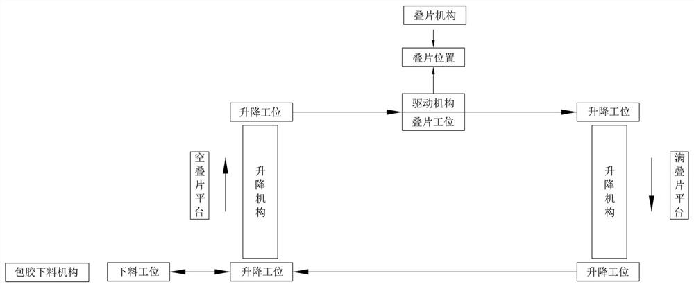
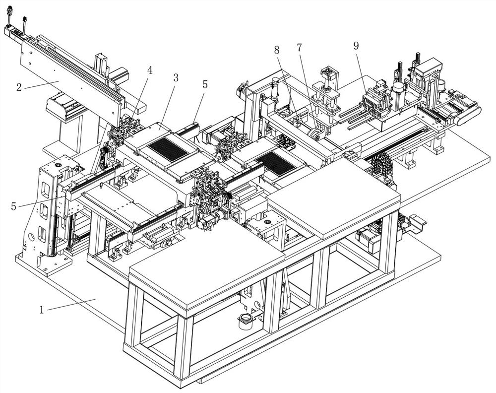
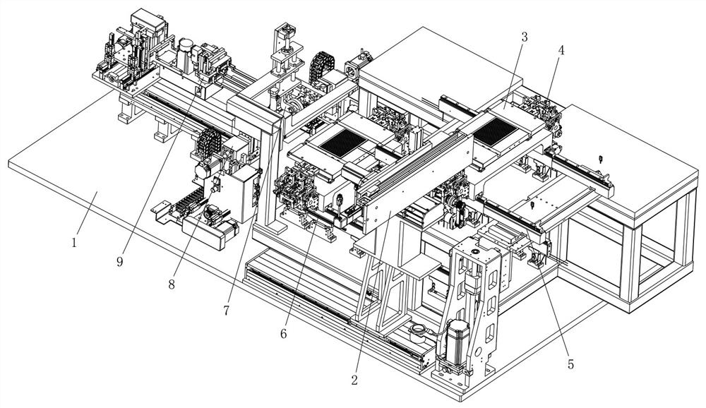
[0065] Such as Figure 1 to Figure 32 As shown, the technical scheme adopted by the present invention is as follows: a platform circulation supply lamination production line, comprising a lamination mechanism 2, a lamination platform 3, a driving mechanism 4, a lifting mechanism 5, a slide rail 6 and a rubber-coated blanking mechanism, Wherein, the above-mentioned slide rail 6 includes an upper slide rail and a lower slide rail arranged at intervals in parallel in the vertical direction, the upper and lower corresponding positions on both sides of the upper slide rail and the lower slide rail are respectively provided with a lifting station, and the upper slide rail is provided with a stacking station. One end of the lower rail is provided with a blanking station; the above-mentioned lamination platform 3 is slidably arranged on the slide rail 6, and is driven by a conveyor...


PUM


Abstract

The platform circulation supply type lamination production line comprises a lamination mechanism, a lamination platform, a driving mechanism, lifting mechanisms, sliding rails and a rubber coating discharging mechanism. The sliding rails comprise an upper sliding rail and a lower sliding rail which are arranged in parallel in a spaced mode in the vertical direction, and lifting stations are arranged on the two sides of the upper sliding rail and the two sides of the lower sliding rail correspondingly. A lamination station is arranged on the upper sliding rail, and a discharging station is arranged at one end of the lower sliding rail. The lamination platform is arranged on the sliding rails in a sliding manner. The two sets of lifting mechanisms are arranged on the lifting stations on the two sides correspondingly. The driving mechanism is arranged at the lamination station, and the lamination mechanism is arranged above the lamination station. The rubber coating discharging mechanism is arranged on the outer side of the discharging station. The lamination platform circularly moves along a rectangular path, so that the capacity of the whole line is greatly improved, the stability of a pole piece group carrying position is ensured, automatic film pressing is realized, interference with pole piece lamination is avoided, continuous rubber pressing is maintained while automatic rubber coating is realized, and the glue coating quality is effectively ensured.

Description

technical field [0001] The invention relates to the field of automation equipment, in particular to a platform circulation supply lamination production line and its circulation lamination process in the field of lithium ion power battery automation production equipment. Background technique [0002] Lithium battery refers to batteries containing lithium in the electrochemical system, including metal lithium, lithium alloys, lithium ions, and lithium polymers. Lithium batteries can be roughly divided into two categories: lithium metal batteries and lithium ion batteries. Lithium battery is a rechargeable battery that mainly relies on lithium ions to move between positive and negative electrodes to work. During charging and discharging, lithium ions intercalate and deintercalate back and forth between the two electrodes: when charging the battery, lithium ions are deintercalated from the positive electrode, inserted into the negative electrode through the electrolyte, and the...

Claims


Application Information

Patent Timeline
IPC IPC(8): H01M10/0585H01M10/04
CPCH01M10/0585H01M10/0404Y02E60/10Y02P70/50
Inventor 唐延弟周贤文宾兴刘成徐骏
Owner SHENZHEN XING GRAIN AUTOMATION CO LTD
Learn More